Are you a connector newbie? Below is a collection of terms relating to connectors with their corresponding definitions.
Attenuation – Decrease in power due to resistance or mismatch in transmission line.
Back Mounted – When applied to a coaxial connector it is that connector mounted from the rear of a panel with the fixing nut on the outside.
Bandwidth – Distance between two frequencies over which a RF or microwave device is intended to work.
Between Series Adaptor – An adaptor used to connect two different generic types of connector.
BNC – Bayonet Nut Connector.
Braid – A weave of metal strands used as an electrical shield for an insulated conductor or group of conductors.

Connector
– The type of connector fitted to a chassis using a single cut-out hole.
Cable Retention – The mechanism that joins the connector to the cable.
Cable Retention Force – The axial force which a connector / cable join can withstand.
Captive – A component such as a contact which is held firmly in position.
Characteristic Impedance – That impedance at which the transmission line is intended to work. A change from the characteristic impedance along its length will cause mismatch and loss of power.
Clamp – The holding of a cable by use of a screw thread action.
Closed Entry Contact – A female contact which is designed to prevent insertion of a contact larger than that specified.
Coaxial Cable – A transmission line where the one conductor is concentric inside another, often abbreviated to “coaxâ€.
Coaxial Termination – A resistive element used to end a coaxial line in its characteristic impedance.
Coaxial Terminator – A device for terminating coaxial cable to a PCB or bulkhead mount (a mechanical device and should not be confused with coaxial termination)
Conhex – Tradename covering SMB and SMC, both in 50 Ohm and 75 Ohm impedance (discontinued)
Connector Durability – The number of times a connector can be physically mated and still maintain its specified performance.
Contact Resistance – The measurement of the DC electrical resistance between a pair of mated contacts. Usually specified as being measured after a given number of mating cycles.
Corona – A discharge of electricity caused by the ionisation of the air around a conductor just prior to total breakdown or flashover.
Crimp – The action of distorting a metal tube to give intimate contact with a conductor; a good crimp should be gas tight and not be impacted by environmental change.
Crimp Dies – The tool inserts which determine the shape of the distortion to create a consistently good crimp.
Crimp Tool – The tool which holds crimp dies to apply the necessary force.
Cross Talk – The amount of signal which may be transferred from one signal carrying line to an adjacent line.
Cut Off Frequency – The frequency at which the loss exceeds a predetermined level.
Decibel (dB) – A unit of measurement of RF power loss.
Dielectric – The insulating medium which holds the center conductor concentric within the connector or cable.
Dielectric Constant – The electrical value of dielectric which determines the impedance in cables or connectors with constant diameters.
Dielectric Withstanding Voltage – The maximum voltage that a dielectric material can withstand without failure.
Direct Solder – A common method of terminating connectors to semi-rigid cable by soldering the cable jacket to the connector.
Discontinuity – A dramatic change in characteristic impedance which gives rise to a reflected wave.
Dissipation – The unused or lost energy in a system e.g. heat.
Distortion – An unwanted change in a signal wave form.
Dummy Load – A device connected to the end of a transmission line to absorb transmitted power and prevent reflected energy.
Dust Cap – A mechanical device attached to the mating face of an unmated connector to prevent ingress of contaminants and provide protection against mechanical damage.
Electromagnetic Compatibility (EMC) – The ability of a device to operate within its intended environment without being effected by or generating electromagnetic interference (EMI).
Engagement and Separation Forces – The forces required to mate and unmate a pair of connectors. The forces are usually specified as a max & min for each action.
Environmentally Sealed – A connector that is provided with seals or other devices to prevent ingress of dust, moisture or other contaminants while mated which might impair performance.
Flexible Cable – A coaxial cable where the outer conductor is flexible (usually braided).
Gigahertz (GHz) – A measure of frequency representing 1 billion Hertz (cycles per second).
Impedance – See ‘Characteristic Impedance’
In-Series Adaptor – An adaptor which enables the connection of two connectors of the same generic type.
Insertion Loss – The loss of power due to a particular component in a transmission line (e.g. cable).
Insulation Resistance – The electrical resistance between two conductors separated by an insulating medium.
Intermodulation – The mixing of two or more frequencies which are not intended to mix.
Interface – The two surfaces of a connector which come into intimate contact when the two halves are mated.
Inter-series Adaptor – See ‘Between Series Adaptor’
Isolation – The measure of interaction between two or more transmission lines.
Jack – One half of a mating pair of connectors. The jack interface normally goes inside the plug interface.
Mean Power – The mean value of the rate at which energy is transmitted from one place to another.
Micro Strip – A transmission line consisting of a flat conductor on a dielectric above a single ground plane. (the ground plane is frequently a metalized face of the dielectric).

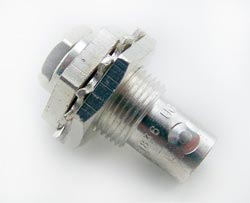
UG909B/U Female Bulkhead Clamp Kings Connector
– Very short electromagnetic waves. Frequency range above 1 GHz.
MIL-C-39012 – The generic specification covering USA Military coaxial connectors.
MIL-C-17 – The generic MIL spec covering coaxial cables.
Mismatch – The condition in which the impedance of the source and load are not the = same. This reduces power transfer and causes reflections.
Mounting Plan – The design of the PCB or panel cut-out used to mount the connector. N Connector – This was the first true microwave connector capable of working to 18GHz, initially designed for test applications.
Nanohex – Trade name covering SSMB & SSMC (discontinued)
Noise – An external electromagnetic signal which interferes with the desired signal.
Non-captive – A component such as a contact which does not have a retention feature.
Passivation – This is a surface treatment applied primarily to stainless steel. The process removes contaminating iron particles and produces a passive surface.
Peak Power – Is the maximum power which may be handled by a connector or cable.
Plug – One half of a mating pair of connectors. The plug interface normally goes outside the jack interface.
POSNS – Abbreviation for “positionsâ€.
PTFE – Abbreviation of polytetrafluorethylene. This is the most commonly used dielectric (insulator) used in professional coaxial connectors.
QPL – Qualified Parts List. Parts approved to MIL-C-390 12 specification.
Receptacle – A term used to describe a connector assembly usually bulkhead or PCB mounted.
Return Loss – A reason for loosing RF energy due to signals being reflected due to a mismatch in a transmission line.
RF Leakage – The RF power lost from a transmission line or device. Measured in dB.
RG – The traditional prefix for MIL spec coaxial cables.
Screw-on – The mating action of connectors which are joined using a screw thread (e.g. SMC)
Sealflex2â„¢ – Cannon trade name for a flexible microwave cable assembly which has a performance similar to semi-rigid cable.
Semi-rigid Cable – A coaxial cable where the outer conductor is a solid metal tube.
Skin Effect – The tendency of alternating currents to flow near to the surface of a conductor; this increases resistance and becomes more marked the higher the frequency.
SMD – Sometimes used as an abbreviation for slide-on variants of SMB. This is a misnomer, the more common use is for Surface Mount Device.
Snap-on – A term used to describe the mating action of SMB and SSMB connectors.
Solderless SMA – An SMA connector that can be connected to semi-rigid cable by compressing the inner body rather than by soldering (sometimes referred to as semi-rigid ‘crimp’ connectors).
Stripline – A method of building a microwave circuit. The circuitry is sandwiched between 2 ground planes. Sometimes referred to as Tri-plate.
Teflonâ„¢ – DuPont tradename for PTFE.
Tensile Strength – The greatest force a device can withstand without tearing or pulling apart. This is frequently the method of determining the effectiveness of a crimp.
TNC – Thread Nut Connector same size as BNC; the only obvious difference is the coupling nut.
Tri-plate – See Stripline.
UG Symbol – Used to indicate a connector made to US government spec.
Voltage Standing Wave Ratio (VSWR) – A way of expressing the resultant loss of power as a result of signal reflections due to discontinuity.


