Tag Archives: Transistors

What are Thermal Transistors?

Modern electronic devices depend on electronic transistors. Although transistors control the flow of electricity precisely, in the process, they also generate heat. So far, there was not much control over the amount of heat transistors generated during operation—it depended on the efficiency of the device—devices with higher efficiency generated lower amounts of heat. Now, using a solid-state thermal transistor, it is possible to use an electric field to control the flow of heat through electronic devices.

The new device, the thermal transistor, was developed by researchers at the University of California, Los Angeles. They published their study in Science, demonstrating the capabilities of the new technology. The lead author of the study explained the process as very challenging, as, for a long time, scientists and engineers wanted to control heat transfer as easily as they could control current flow.

So far, engineers cooled electronics with heat sinks. They used passive heat sinks to draw excess heat away from the electronic device to keep it cool. Although many have tried active approaches to thermal management, these mostly rely on moving parts or fluids. They can take typically from minutes to hours to ramp up or down, depending on the thermal conductivity of the material. On the other hand, using thermal transistors, the researchers were able to actively modulate the heat flow with higher precision and speed. The higher rate of cooling or heating makes thermal transistors a promising option for thermal management in electronic devices.

Similar to the working of an electronic transistor, the thermal transistor uses electric fields to modulate its channel conductance. However, in this case, the conductance is thermal, rather than electrical. Researchers engineered a thin film of molecules in the form of a cage to act as the transistor’s channel. They then applied an electric field, making the molecular bonds stronger within the film. This, in turn, increased its thermal conductance.

As the film was only a single molecule thick, the researchers could attain maximum change in conductivity. The most astonishing feature of this technology was the speed at which the change in conductivity occurred. The researchers were able to go up to a frequency of 1 MHz and above—this was several times faster than that achieved by other heat management systems.

Other types of thermal switches typically control heat flow through molecular motion. However, compared to the motion of electrons, molecular motion is far slower. The use of electrical fields allowed the researchers to increase the speed of electrons in the switch from mHz to MHz frequencies.

Another difference between molecular and electron motion is that the former cannot create a large enough difference in thermal conduction between the on and off states of the transistor. However, with electron motion, the difference achieved can be as high as 13 times, an enormous figure, both in speed and magnitude.

Because of this improvement, the device assumes an important status for cooling processors. Being small, the transistors use only a tiny amount of power to control the heat flow. Another advantage is that it is possible to integrate many thermal transistors on the same chip.

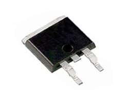
New Clearance Categories and Products!

We are finally updating our clearance categories. We’ve added lots of new products to the subcategory pages including:

Click on the links above to see all the new products that have been added!

How Does Switching Affect Semiconductors?

Even though ICs rule the world of electronics, the transistor does all the work. Within each IC are millions upon millions of transistors perpetually switching on and off so that the IC can carry out its intended functions. Even if one of the multitudes of transistors were to stop switching, the IC could lose part or all of its functionality.

Circuits handling digital signals most often use transistors to switch from a high state to a low state and vice versa. It is usual to call a circuit point as being in a high state if the voltage at that point is close to the supply voltage. If the circuit point is closer to the ground or zero voltage, we generally call it as being at a low state. The time taken for the transistor to switch from a high to a low state or vice versa is its switching rate. While the transistor does not expend much energy when at either the low or the high state, the same cannot be said for the time when it is actually switching.

Under ideal conditions, a transistor should switch instantaneously. That means the transistor should take zero seconds to change its state. However, ideal conditions do not happen in reality and the transistor takes a finite time, however small, to actually switch over.

Transistors are made of semiconductor material and each junction has a finite capacitance and resistance. Junction capacitances store energy and the combination of resistance and capacitance acts to slow down switching – the capacitance must fill up or empty itself before the transistor can flip. The rate at which the capacitance fills up or empties itself depends on the junction resistance.

The situation gets worse as the switching frequency goes up. As the transistor is driven to toggle faster and faster, the junction capacitance may not get enough time to discharge or charge up fully. That defines the maximum switching rate the transistor can achieve.

Semiconductor manufacturers use various methods to reduce junction capacitances and resistances to induce these special semiconductors switch faster. Although modern semiconductors (transistors and diodes) are capable of switching at MHz or GHz scales, the cumulative effect of the tiny switching losses add up to increase the junction temperature.

Power is the product of voltage and current. When a semiconductor is in a high state, although the voltage is high, the current is negligible and consequently, the power drawn from the supply is negligible. When the semiconductor is a low state, its voltage is close to the ground level and the product of current and voltage is again negligible.

However, during switching, when the voltage is somewhere in-between the supply and ground levels, the current drawn also increases. That makes the product of voltage and current have a significant value and the semiconductor generates heat because of the power consumption. With higher frequencies, this happens more frequently and the heat accumulates to produce higher junction temperature.

If the natural process of heat dissipation can remove the accumulated heat, the semiconductor soon reaches a steady temperature. Else, heatsinks and or forced cooling methods are necessary to remove the heat accumulated.

How RTPs Help To Save Expensive PCBs from Thermal Runaway PowerFETs

powerfetAlthough powerFETs or power Field Effect Transistors are very robust devices used in the automotive industry – they have their limitations. In the automotive environment, powerFETs go through the tortures of extreme temperature variations together with severe thermo-mechanical stresses. They face noisy short circuits, high arcing, intermittent shorts as well as inductive loads. These shocks can fatigue the device over time, and it can fail in a short, an open or resistive mode.

For example, if the maximum operating voltage of a powerFET is exceeded, failure happens very quickly. The powerFET goes into an avalanche breakdown once the voltage rating goes beyond the maximum allowed. If the energy within the transient overvoltage is more than the rated avalanche energy level, the device will start to fail resulting in generation of smoke, flame or it may even be de-soldered.

In some cases, the powerFET while failing may generate precarious temperatures through I2R heating. This may cause a thermal runaway for the device, but the resulting current may not be large enough to cause failure of a standard fuse protecting the powerFET. This mode of failure is of particular concern, for not only the powerFET, but also for the PCB or the Printed Circuit Board. A power of as little as 10 Watts may generate localized hot spots of above 180°C, which can damage the glass PCB’s epoxy structure leading to a thermal event.

Tyco Electronics has developed a Reflowable Thermal Protection or RTP, which is a reliable and robust surface mount thermal protector to prevent thermal damage on PCBs caused by failing power electronics. This is a secondary thermal protection device, which can replace several components such as redundant powerFETs, heavy heat sinks and relays currently used for such protection in the automotive designs.

To work effectively, the RTP device has to be placed in series and on the power line, very close to the FET. This allows the device to track the temperature of the FET and disrupt the current by opening the circuit before the thermal runaway condition generates a thermally destructive condition on the PCB. Under normal conditions, the RTP device has a low resistance, typically about 0.6mOhm.

Whenever the RTP device detects the generation of unsafe temperatures because of the failure of a power component or any other board defect, it interrupts the current and prevents a thermal runaway condition that could lead to critical damage. An RTP200 device typically opens (high resistance condition) at 200°C, which is a temperature above the normal operating temperature, but below the Lead-free solder reflow temperature.

It may seem like a paradox that the RTP device operates at 200°C but can withstand Lead-free soldering temperatures of 220°C. This is because the RTP is not in an active state unless it has been armed by passing a specific current through it for a specified amount of time. Before it is armed, the RTP can withstand three Lead-free solder reflow steps before it operates. The electronic arming procedure is one-time only and can be implemented to occur automatically or during system testing.