Tag Archives: transistor

What Is An Electronic Load And Where Do You Use It?

Power supply manufacturers need to test their products dynamically. Instead of using fixed-resistor banks of different sizes, electronic loads allow them to simulate easily and quickly various power states. Using an electronic load, large ranges of power sources such as converters, inverters, UPSs and electromechanical sources such as batteries and fuel cells may be tested. For varying loads, electronic loads are easier to use and provide a much higher throughput compared to fixed-resistors.

For example, a handheld device may have to be tested for sleep, power conservation and full power modes. These are easier to test using a single electronic load, but may require several combinations of fixed-resistors. Additionally, an electronic load may be programmed to represent closely a real environment for a power source. This may take the form of modulation to improve the performance of power supplies by providing a faster transient response as compared to a standard power supply.

An electronic load usually consists of a bank of power transistors, power MOSFETs or IGBTs mounted on a suitably sized heat sink, and cooled with fans. An electronic circuit governs the amount of current that the power devices can draw from the power supply on test. To protect the power devices from damage, electronic loads usually have a pre-settable power limit. The manufacturer usually provides a power curve for the safe operation of an electronic load. The user must be aware of the simultaneous maximum voltage and current that can be applied to the electronic load to ensure the electronic load is not overpowered.

It is important to select a suitable electronic load for the testing. For example, a power supply rated for 12V and 30A, may never be operated at 12V and 30A continuously. While testing, the operator may run it at 12V and 5A and then at 3V and 30A. That means an electronic load of 90-100W is sufficient to test the supply.

To improve the performance of a power supply, an electronic load may be used as a high-speed current modulator. In such cases, only a fraction of the power rating of the power supply is required. When the current is modulated to the highest level, the voltage across the load is likely to be very low. As the current is modulated off, the voltage rises to its maximum. Usually, if the modulation of the current is from zero to some maximum, the load power required is one-quarter of the operating voltage times the current rating with some margin added.

Electronic loads are very useful for dynamically testing power sources. In this form of testing, the current is quickly pulsed between two states, simulating a possible sleep mode and a full power mode of a device. This pulsing can be as fast as 20,000 times a second.

Another requirement that electronic loads are adept at is low voltage testing. Although most electronic loads will refuse to operate when the applied voltage is below 1V, there are some models, which perform comfortably down to 0.6V. This is a very useful feature when testing fuel cells where the operation at low voltages is crucial.

Transistors: What Is The Difference Between BJT, FET And MOSFET?

BJTs, FETs and MOSFETs are all active semiconductor devices, also known as transistors. BJT is the acronym for Bipolar Junction Transistor, FET stands for Field Effect Transistor and MOSFET is Metal Oxide Semiconductor Field Effect Transistor. All three have several subtypes, and unlike passive semiconductor devices such as diodes, active semiconductor devices allow a greater degree of control over their functioning.

Depending on their subtypes, operating frequency, current, voltage and power ratings, all the three types of transistors come in a large variety of packages, and all of them are susceptible to ESD or Electro Static Discharge. That means when you handle these devices, you must take adequate precaution against static charges destroying them.

he basic construction of a BJT is two PN junctions producing three terminals. Depending on the type of junctions, the BJT can be a PNP type or an NPN type. The three terminals are identified as the Emitter or E, the Base or B and the Collector or C. BJTs usually function as current controlling switches. The three terminals can be connected in three types of connections within an electronic circuit – Common Base configuration, Common Emitter configuration and Common Collector configurations. All the three connections have their own functions, merits and demerits. The BJT is Bipolar because the transistor operates with both types of charge carriers, Holes and Electrons.

The FET construction does not have a PN junction in its main current carrying path, which can be made from an N-type or a P-type semiconductor material with high resistivity. A PN junction is formed on the main current carrying path, also called the channel, and this can be made of either a P-type or an N-type material. The three leads of a FET are the Source (S), Drain (D) and Gate (G), with Source and Drain forming the ends of the channel and the Gate controlling the channel conductivity. Unlike the BJT, the FET is a unipolar device since it functions with the conduction of electrons alone for the N-channel type or on holes alone for a P-channel type.

The input impedance at the gate of an FET is very high, unlike the BJT, which comparatively has much lower impedance. Additionally, the conductivity of the channel depends on the voltage applied to the Gate, essentially making it a voltage-controlled device, unlike the BJT, which is current-controlled. The voltage applied to the Gate controls the width of the channel, allowing the FET to carry current between the Drain and Source pins. The Gate voltage that cuts off the current flow between Drain and Source is called the pinch off voltage and is an important parameter.

The MOSFET is a special type of FET whose Gate is insulated from the main current carrying channel. It is also called the IGFET or the Insulated Gate Field Effect Transistor. A very thin layer of silicon dioxide or similar separates the Gate electrode and this can be thought of as a capacitor. The insulation makes the input impedance of the MOSFET even higher than that of a FET. The working of the MOSFET is very similar to the FET.

You can read more about transistors in depth here.

What is a MOS-FET?

Mos-FETMOS-FET, which is an abbreviation of Metal-Oxide-Semiconductor Field Effect Transistor, is a very important kind of transistor. Many IC’s are constructed of arrays of MOS-FETS on a tiny sliver of silicon.

They are very small, easy to manufacture and many MOS-FETS consume a small amount of power making them an excellent choice for many applications.

It is the most common type of transistor available for either digital or analog circuits, replacing the bipolar transistor which was much more common in the past.

The word ‘metal’ in the name is actually now a misnomer because what was originally the gate material (often Aluminum) is now more often a layer of polysilicon (aka polycrystalline silicon).

BUZ11 – a Popular Power MOSFET

BUZ11

BUZ11

The BUZ11 is an N-Channel enhancement mode silicon gate power field effect transistor designed for applications such as switching regulators, switching converters, motor drivers, relay drivers, and drivers for high power bipolar switchng transistors requiring high speed and low gate drive power. The BUZ11 is also used for DC-DC and DC-AC converters and in the automotive environment for injection, ABS, airbags, lampdrivers and more.

It features:

  • 33A 50V
  • Nanosecond Switching Speed
  • Linear Transfer Characteristics
  • High Input Impedance

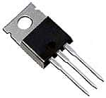
The BUZ11 is in a TO220 package.

If you are looking at the BUZ11 with the drain (flange) at the top, the left pin is the GATE, the middle is the DRAIN, and the right lead is the SOURCE.

What is Transistor-Transistor-Logic – TTL?

TTL Transistor-Transistor-Logic

TTL Transistor-Transistor-Logic


TTL or Transistor-Transistor Logic is a type of digital circuit that is made from BJT or bipolar junction transistor along with resistors. Both the amplifying function and the logic gating function are carried out through transistors, thus the name transistor-transistor logic.

TTL is used for many applications like industrial controls, computers consumer electronics, test equipment, synthesizers and more. The TTL designation is also used in some places to imply ‘compatible logic levels’ even if they are not directly associated with transistor transistor logic circuits.

James Buie invented the Transistor Transistor Logic in 1961 and the first Transistor-Transistor Logic devices were made in 1963 in Sylvania. These devices were called the “Sylvania Universal High-Level Logic family” and were used within controls for the US Phoenix missile. In 1964 Texas Instruments produced ICs of 5400 series and later on, the 7400 series which made the Transistor-transistor Logic devices popular amongst electronic system designers. The 7400 series went on to become the industry standard. Many companies like AMD, Motorola, Intel, Fairchild, Siemens, National Semiconductor made compatible parts.

The TTL circuits were low cost which made them highly practical for using digital techniques in tasks which were earlier done through analog methods. One of the first computers that was built, in 1971, made use of the transistor transistor logic instead of a microprocessor chip which at that point of time was not available. With time incremental improvements in power consumption and speed were made, and the last popular series was the 74AS/ALS Advanced Schottky was made available in 1985.