Tag Archives: Switches

New Clearance Categories and Products!

We are finally updating our clearance categories. We’ve added lots of new products to the subcategory pages including:

Click on the links above to see all the new products that have been added!

Switches & Latches Based on Hall Effect

Switches and latches based on the Hall effect compare magnetic fields. More correctly, they compare the B-field, or the magnetic flux density with a pre-specified threshold, giving out the comparison result as a single-bit digital value. It is possible to have four categories of digital or on/off Hall sensors—unipolar switches, omnipolar switches, bipolar switches, and latches.

Each of the above switches/latches has a unique transfer function. However, this depends on an important concept—the polarity of the magnetic flux density. The polarity of the B-field makes the Hall effect devices directional. Moreover, it is sensitive only to that component of the magnetic flux density that happens to be along its sensitivity axis.

When a component of the magnetic field applied to a device is in the direction of its sensitivity axis, the magnetic flux density is positive. However, if the component is in the opposite direction of the sensitivity axis, the polarity of the -field is negative at the sensor.

Hall sensor manufacturers follow another convention for the B-field polarity. They consider the magnetic field from the south pole of a magnet as positive, while that from the north pole, as negative. They base their assumption on the branded face of the sensor facing the magnet. The branded face of the Hall sensor is the front surface bearing the device part number.

Therefore, for a sensor with a SOT23 package, the sensitivity axis is perpendicular to the PCB. Whereas for a sensor with a TO-92 package, the sensitivity axis will be parallel to the PCB, provided the sensor is upright after soldering.

A unipolar switch has its thresholds in the positive region of the B-field axis. Its output state changes only when the south pole of a magnet comes near it. Bringing the north pole or a negative field close to the sensor produces no effect, hence the name unipolar.

When the sensor is off, its output is logic high. Gradually bringing a south-pole closer to the sensor causes the device to switch to a logic low as the magnetic field crosses its threshold. The opposite happens when the south pole gradually moves away from the sensor. However, as the threshold of switching for a decreasing magnetic field is different from the threshold of switching for an increasing magnetic field, the device shows a hysteresis effect. Manufacturers create this hysteresis deliberately to allow the sensor to avoid jitter.

An omnipolar switch responds to both—a strong positive field and a strong negative field. As soon as the magnitude of the magnetic field crosses the sensor’s threshold, it changes state. With omnipolar switches, the magnitude of the operating point is the same irrespective of the polarity of the B-field. However, the magnitude of the release point is different from the operating point, but the same for both polarities. Hence, the omnipolar switch also has a hysteresis effect.

A latch device turns on by an adequately large positive field but turns off only by an adequately large negative field. A bipolar switch behaves as a latch device, but its exact threshold values may change from device to device.

What are Tactile Switches?

Tactile switches are electromechanical switches that make or break an electrical circuit with the help of manual actuation. In the 1980s, tactile switches were screen-printed or membrane switches that keypads and keyboards used extensively. Later versions offered switches with metal domes for improved feedback, enhanced longevity, and robust actuation. Today, a wide range of commercial and consumer applications use tactile switches extensively.

The presence of the metal dome in tactile switches provides a perceptible click sound, also known as a haptic bump, with the application of pressure. This is an indication that the switch has operated successfully. As tactile switches are momentary action devices, removal of the applied pressure releases the switch immediately, causing the current flow to be cut off.

Although most tactile switches are available as normally open devices, there are normally closed versions also in the market. In the latter model, the application of pressure causes the current flow to turn off and the release of pressure allows the current flow to resume.

Mixing up the names and functions of tactile and pushbutton switches is quite common, as their operation is somewhat similar. However, pushbutton switches have the traditional switch contact mechanism inside, whereas tactile switches use the membrane switch type contacts.

Their construction makes most pushbutton switches operate in momentary action. On the other hand, all tactile switches are momentary, much smaller than pushbutton switches, and generally offer lower voltage and current ratings. Compared to pushbutton switches, the haptic or audible feedback of tactile switches is another key differentiator from pushbutton switches. While it is possible to have pushbutton switches in PCB or panel mounting styles, the design of tactile switches allows only direct PCB mounting.

Comparing the construction of tactile switches with those of other mechanical switches shows a key area of difference, leading to the tactile switches being simple and robust. This difference is in the limited number of internal components that allows a tactile switch to achieve its intended function. In fact, a typical tactile switch has only four parts.

A molded resin base holds the terminals and contacts for connecting the switch to the printed circuit board.

A metallic contact dome with an arched shape fits into the base. It reverses its shape with the application of pressure and returns to its arched shape with the removal of pressure. This flexing process causes the audible sound or haptic click. At the same time, the dome also connects two fixed contacts in the base for the completion of the circuit. On removal of the force, the contact dome springs back to its original shape, thereby disconnecting the contacts. As the material for both the contacts and the dome are metal, they determine the haptic feel and the sound the switch makes.

A plunger directly above the metallic contact dome is the component the user presses to flex the dome and activate the switch. The plunger is either flat or a raised part.

The top cover, above the plunger, protects the switch’s internal mechanism from dust and water ingress. Depending on the intended function, the top cover can be metallic or other material. It also protects the switch from static discharge.

What is a DIP Switch?

DIP or Dual-In-line-Package switches have been popular since the 1970s. OEMs and end-users use them widely to change the functionality of electronic devices at the point of use. For instance, DIP switches allow users to set region codes for equipment to make them work in different areas, to change to a specific radio channel, which garage door the opener will engage, or to select the type of memory a PC motherboard has.

The DIP switch comprises a set of switches within a single unit, typically mounted on a PCB. Each switch is very basic in construction and functionality. The user must set each switch manually, and therefore, the user can simply determine the status by viewing the switch bank during system startup. This is in direct contrast to a membrane keypad connected to a microcontroller, which must be powered up and polled to know the status. Therefore, DIP switches have the simplicity and provide input to basic system firmware, and need not be powered up to know their current status.

Users can select the number of operations on their DIP switch depending on the configuration of the electronic application. This is possible as DIP switches are available in a variety of sizes, configurations, power ratings, and styles.

Just like any other switch, users can select from the number of poles and throws the DIP switch must-have. For instance, they can use the SPST switch or single pole single throw switch, as it has a two-terminal option, with the pole either engaging with the throw to enable continuity or disengaging with the throw to enable electrical isolation.

Likewise, there are SPDT switches or single pole double throw switches, where the user may push the single pole to engage with any one of the throws, and push it the other way to engage with the other throw. It is possible to direct any signal on the pole to either one of the throws at any time.

Other switches are available as a combination of the above SPST and SPDT arrangements. For instance, there may be mechanically linked double poles engaging with double throws, making the switch DPDT or double pole double throw type.

Typically, the number of switches in a package is dependent on the application, with 1 to 16 positions being a common number. For instance, a common DIP switch package may have eight positions, allowing it to be set to 256 different ways. This is equivalent to the 256 binary values that an eight-bit byte may express.

Mechanically, DIP switches are available in various types, depending on the way they operate, whether they have slide actuators, rotary actuators, piano actuators, and so on.

DIP switches with slide actuators usually have two positions, either closed or open, acting as an SPST switch. However, there can be DIP switches with slide actuators and three positions. Frequently, in such switches, the middle position acts as the neutral. As the actuator moves to either side, it makes contact with the position on that side.

DIP switches are low-cost, flexible, and provide a simplicity rarely found.

Why Smart Home Tech Adoptions Need Switches

Most modern homes now use connected devices for entertainment, access control, and several other daily tasks. Their rapid increase can be gauged from the growth of the US market for smart homes, which has reached 29 million and is still rising.

The amazing features and efficiencies products related to smart homes offer to households naturally mesmerize consumers. However, this also necessitates engineers keep in mind the physical interfaces. While customer satisfaction is a long-standing effect, the immediate look and feel of the device dictates its price. This implies details are an important aspect, where the choice of every component matters and that includes switches and buttons.

Most people tend to ignore switches and buttons, forgetting they are responsible for driving the technical movement known as smart homes. However, a few important reasons establish engineers designing home products must give them a serious thought.

The connected devices in a smart home depend critically on their hardware designs. These include switches, sensors, screens and other components used on smart televisions, smart thermostat controls, connected door locks, and more. Most importantly, a user’s overall satisfaction comes from the way a product feels or the tactile sensation it generates.

Most of the time, a customer’s first interaction with the control of a product comes from its on/off switch, which a user physically touches. Unless the switch creates a delightful experience, the customer is likely to search for another product that offers a better feeling.

Cameras working on the Internet Protocol are now commonly available in smart homes. The reason for this is easy to figure out, as according to the statistics provided by iControl Networks, there is a burglary happening every 14.1 seconds in the US. With an IP camera installed, a person can monitor the activity at home from a remote location on their smartphones, laptops, or any other smart device. The very presence of IP cameras act as a deterrent to crime, apart from helping the police apprehend criminals, while simply providing a piece of mind to a homeowner.

However, smart cameras need the right switch to power and protect them. Usually, this is a miniature tactile switch, suitable for meeting the shrinking form factors of the device. Often smaller than the small lens display used by these cameras, the switch must be robust enough to prevent intruders from breaking it and rendering the camera useless.

While IP cameras capture images of unwelcome intruders whom people are not suspecting of entering their homes, access controls offer an additional level of security to the majority of consumers concerned with privacy and security in their smart homes. Access controls are usually equipped with internet doorbells with built-in cameras, and smart door locks.

While the camera shows an image of the person at the door, the smart lock allows unlocking the door remotely. This arrangement can be handy if the door has to be opened for the baby sitter or for the teenager who has misplaced his keys. Usually, the smart lock has a miniature switch to set or reset it. This switch has to be small but long lasting, and able to withstand harsh conditions such as humidity and rain.

ISO 7000 compliant Fully Illuminated Push Button Switches

The Vista-based company APEM, Inc., from California, has developed a new series of fully illuminated push button switches that meet the ISO 7000 standards in all respects. These are the FP30 series pushbuttons. These are being offered to users in both threaded bush mounting form and snap-in type. Even though the size is rather large, they are very light. For snap in types, the panel thickness ranges from 1.5mm to 2.5mm and the threaded type support 1mm to 9mm panels. The unique feature of the FP30 series push buttons is that they are illuminated. They are offered in smooth, glossy finish. The users have the choice of many bezel colors and with differently colored actuators.

The FP 30 series push buttons have the option of being pad printed or even laser etched with more than 100 symbols. The ISO 7000 standards allow the use of graphical symbols on the equipment and FP 30 series complies with this. They are available in seven LED colors meeting the user’s needs and offered in 48V, 24V and 12V ranges. Choice of momentary or latching is available for both threaded bush type and snap-in type along with the option of single pole or double. The push button can be used for 400,000 mechanical operations or 1 million electrical operations when operated at 200mA at 12VDC.

Although the new FP 30 series push buttons are illuminated, non-illuminated push buttons in the FP30 series are also available. The standard packing has 20 pieces. The color options vary marginally for bezel, LED and actuator. For example, you can select a bright chrome bezel with an orange option for the actuator. The case material used is nylon grade PA46, while for the actuator it is PA12 with gloss finish. The bezel is gloss finish ABS, while the bushings and the contacts may be in code 2 silver for 4A 12VDC, code 4 silver or gold plated for 200mA 12VDC. The operating temperature is between -40ºF and +167ºF or -40ºC and +75ºC. Lug terminals are open to soldering.

The new FP 30 series push buttons have a very wide range of applications. They have been designed to make an impact in various industries such as security, industrial automation, defense, medical, instrumentation, apart from being considered ideal for dashboards in the automotive, passenger and commercial vehicle segments. Customer specific requirement of symbols and marking color is also considered on receipt of a specific request and attended to expeditiously.

The company APEM started its operation in the year 1952, manufacturing industrial switches. Over the years, it has grown multifold in a very rapid manner to reach out globally and is now one among the leading manufacturers of man machine interfaces. With a presence in 11 countries and with global distribution network and agents, the company has 67% of its total turnover as exports. APEM designs for professional switches and manufactures them to cater to diversified markets including, medical, industrial automation, defense, communications, instrumentation and transport. The latest launch of the FP30 series of push buttons complying with ISO 7000 standards is another milestone for the company and is expected to make a significant impact in the market.

Rotary Switches: Construction and Use

A rotary switch is a kind of switch that has a rotating shaft attached to a terminal. That terminal is able to make or break a connection to one (or more) other terminals. Rotary switches may feature different switch positions that can be set by rotating the switch spindle in one or another direction. Some common examples where a rotary switch might be used is in a multi-speed fan or as a band selector on multi-band radios. Until the early 1970’s, rotary switches were used as channel selectors on TV receivers.

In general, rotary switches can be found where ever there is a need to control a large number of circuits covering a range of currents, voltages and power requirements. Currently, you will find rotary switches in these applications:

  1. medical equipment
  2. computers
  3. industrial controls
  4. instrumentation
  5. communications equipment
  6. aircraft equipment

The construction and design of a rotary switch is centered around the center rotor. The rotor has a contact arm that projects out from its surface. Around the rotor are an array of terminals. These serve as the contact for the arm, or spoke. Since the switch has multiple layers, each layer permits the use of an additional pole. There is also a detent mechanism which will click into place as the switch is turned from one active position to another. The contact / sensor system and detent mechanism determine the number of possible switching combinations.

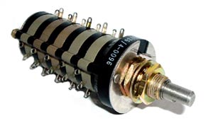
Grayhill Rotary Switch

Grayhill Rotary Switch


Above is an example of a Grayhill military rotary switch. You can see it has 5 decks. Each deck has 1 pole. Each pole has 9 positions.

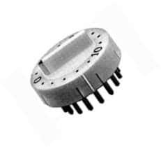
This is an example of a 16 position rotary switch assembly 1-435304-1. This rotary switch assembly has a bar handle. It is a single pole but has 16 positions.

Tact Switch – SKPFABA010

We’ve been selling a lot of this one particular switch – it’s called a long travel tact switch; manufactured by ALPS.

Here are some of the features of this switch:
— Dimensions: 8mm x 8mm
— Suitable for automotive applications due to its high operational force
— Malfunctions are prevented due to it having a longer travel than most conventional tact switches
— Easily mounted on a PC board with snap in leads
— Some of the output terminals can be used as jumper leads which makes the circuit arrangement simple

Here are some other uses:
— automotive electronic equipment
— communication devices
— measuring instruments

These switches are available right now – they have been priced lower than any other distributors.

Be sure to check them out next time you need a 12V tact switch!