Tag Archives: solder

What is Soldering?

Although soldering electronic components in place is a complex activity, most people involved with the soldering process do not realize it. Complicated chemical and thermal processes occur within a very small space when soldering. To make a good solder joint, it is necessary to follow a few basic rules.

Apart from just making good electrical contacts, solder joints should also be mechanically strong and must not oxidize. Additionally, there should not be chemical residues in the joint. Usually, chemical residues come from flux, which can corrode plastic and metallic surfaces both.

Manufacturers offer solder in three categories—consumer, industrial, and high-end. The automotive and health industry makes use of the third category. Consumer and industrial grades are more common for manual, automated, and other construction purposes.

For several years, the standard was the leaded solder. With a relatively low melting point of around 183 °C, leaded solder has good flow and wetting characteristics. For proper melting and formation of a good solder joint, the recommended temperature at the tip of a soldering iron is 120 °C above the alloy’s melting temperature. This corresponds to a tip temperature of about 300 °C.

Manufacturers provide flux inside the hollow of the solder wire. The flux helps to dissolve oxides of the metals at the solder joint. General purpose leaded solder is typically an alloy of tin and lead in the ratio 63:37. Typically, the tin in the alloy amalgamates with the metal (typically copper), producing an alloy of the two metals, as an intermetallic diffusion zone. This helps to form a good solder joint, well-formed, mechanically strong, and durable.

However, an ideal solder joint does not happen in all cases. Sometimes, the solder forms a cold solder joint. Reasons for the formation of a cold solder joint are the presence of highly oxidized metals and dirt, inadequate heating, or fast cooling after the melting process. Inadequate wetting is common in cold solder joints, leading to easy detachment of components.

It is easy to recognize a cold solder joint with leaded solder. The joint has a dull matte surface against a shiny, glossy surface of a good solder joint. With lead-free solder, this is no longer the case. Newer alloys of lead-free solders usually form a matte surface. However, this depends on the specific composition, and it remains matte whether the solder is establishing a good or a cold joint.

New lead-free solders are RoHS compliant, meaning they do not contain certain hazardous substances, as specified by the EU Directive and the Restriction of Hazardous Substances.

The lead content in lead-free solder cannot cross a 0.1% limit. The intention is to prevent the operators from inhaling toxic vapors. Earlier, the use of suitable extraction systems prevented the risk of such inhalation, provided they were in actual use.

The absence of lead in lead-free solders has resulted in an increase in their melting point. The presence of about 95% tin raises the melting point of the alloy from ~217 °C to ~227 °C. This also changes the flow characteristics. Higher temperatures mean the actual soldering time must be small to prevent damage to the components.

What makes a Soldering Iron?

Solder, usually an alloy of lead and tin, has a low melting temperature. Placed between two metallic objects and heated, solder melts and wets the two metallic surfaces. On cooling, solder forms a bond between the two objects. Originally, a heated iron piece brought the solder to its melting point, hence the name soldering iron. Later, people found copper to be a better replacement for iron piece.

People working with electronic components are the biggest users of the soldering iron today. To suit their needs, the soldering iron has had to undergo several improvements. The latest models can be those of the uncontrolled type or ones where the user can set the temperature of the tip.

The simplest form of uncontrolled soldering iron has an insulated hollow handle that has an electric cable passing through. One end of the cable terminates in a resistive heating coil wrapped around an iron rod, but insulated from it by a layer of mica. A metal tube attached to the handle and insulated from the heater protects the user from the heating coil. At the front of the iron rod, there is a special copper tip that heats up when electricity is allowed to flow through the heating coil. When the tip is sufficiently hot, it is able to melt a solder.

There are several disadvantages of the uncontrolled soldering iron. The continuous heating of the tip causes a layer of oxides to form on it, reducing its ability to melt solder, unless the oxide layer is frequently scraped off. Solder reacts with the impurities in the copper tip and causes pits to appear on its surface. This requires occasional filing to keep the tip free of pits. Some components are temperature sensitive and can be damaged because the soldering iron tip touching them while soldering is much hotter than they can withstand.

The above disadvantages led to the development of temperature-controlled soldering irons, where a temperature feedback from the tip controlled the power fed into the heater, enabling the tip to remain at a certain temperature. By controlling the amount of feedback, the user now had the ability to allow the tip to become cooler or heat up further.

The tip too underwent a lot of change. Rather than use a copper piece throughout, the tip was made with multiple layers of different metals, such as iron, aluminum, and hardened copper. A soldering station helped to house the control electronics to set and adjust the tip temperature, as well as to detect when the iron was actually resting between two bouts of active soldering so the control electronics could reduce the tip temperature at times of rest. As soon as the user picked up the soldering iron, the control electronics pumped in more power input to bring the tip temperature quickly up to the set point.

Earlier, the control electronics for the soldering iron was predominantly analog. The latest models feature a digital control. Analog control was simple where the user could turn a knob to set the temperature. However, the digital ones have more features. Apart from a digital display showing the tip temperature in either Centigrade or Fahrenheit that the user can select, the soldering stations usually have a few preset selections.

What is Vapor Phase Reflow Soldering?

Vapor Phase Reflow Soldering is an advanced soldering technology. This is fast replacing other forms of soldering processes manufacturers presently use for assembling printed circuit boards in high volumes for all sorts of electronic products. Soldering electronic components to printed circuit boards is a complex physical and chemical process requiring high temperatures. With the introduction of lead-free soldering, the process is more stringent, required still higher temperatures and shorter times. All the while, components are becoming smaller, making the process more complicated.

Manufacturers face soldering problems because of many reasons. Main among them is the introduction of lead-free components and the lead-free process of soldering. The other reason is boards often can contain different masses of components. The heat stored by these components during the soldering process varies according to their mass, resulting in uneven heat distribution leading to warping of the printed boards.

With Vapor Phase reflow soldering, the board and components face the lowest possible maximum temperatures necessary for proper soldering. Therefore, there is no overheating of components. The process offers the best wetting of components with solder and the soldering process happens in an inert atmosphere devoid of oxygen – resulting in the highest quality of soldering. The entire process is environment friendly and cost effective.

In the Vapor Phase Reflow Soldering process, the soldering chamber initially contains Galden, an inert liquid, with a boiling point of 230°C. This is same as the process temperature for lead-free Sn-Ag solders. During start up, Galden is heated up to its boiling point, causing a layer of vapor above the liquid surface, displacing the ambient air upwards. As the vapor has a higher molecular weight, it stays just above the liquid surface, ensuring an inert vapor zone.

A printed circuit board and components introduced in this inert vapor zone faces the phase change of the Galden vapor trying to cool back its liquid form. The change of phase from vapor to liquid involves the release of a large amount of thermal energy. As the vapor encompasses the entire PCB and components, there is no difference in temperature even for high-mass parts. Everything inside the vapor is thoroughly heated up to the vapor temperature. This is the biggest advantage of the vapor phase soldering process.

The heat transfer coefficients during condensation of the vapor ranges from 100-400Wm-3K-1. This is nearly 10 times higher than heat transfer coefficients involved in convection or radiation and about 10 times lower than that with contact during liquid soldering processes. The excellent heat transfer rate prevents any excessive or uneven heat transfer and the soldering temperature of the vapor phase reflow process stays at a constant 235°C.

There are several advantages from the Vapor Phase Reflow Soldering process. Soldering inside the vapor zone ensures there can be no overheating. As the vapor completely encompasses the components, there are no cold solders due to uneven heat transfer and shadowing. The inert vapor phase process precludes the use of nitrogen. Controlled heating up of the vapor consumes only one-fifth the usual direct energy consumption, and saves in air-conditioning costs.

As the entire process is a closed one, there is no creation of hazardous gasses such as from burnt flux. Additionally, Galden is a neutral process fluid and environment friendly.

How to solder like a pro

Manual soldering is a skill that gets better with practice. For those who are starting out for the first time, manual soldering can be risky, unless they take proper care and follow safety instructions. Manual soldering involves application of heat locally by a soldering iron, whose tip may reach temperatures as high as 400°C. Soldering materials are sometimes toxic, especially if using lead based solders. Some very useful information about soldering can be found here.

One of the best tips to follow for both starters and experienced people is to don safety glasses before starting to solder. This is something that should become a habit for everyone who is soldering, because hot solder entering the eye can be dangerous. A wire, bent the wrong way, can easily flick hot solder into the air. When cutting a component leg, the cut piece can travel at high speeds. Safety glasses will save the eyes from all these flying missiles.

For most people, soldering skills will not be very good at first, but will certainly improve over time. There is no magic in making perfect solder joints every time, you will simply get used to how to hold things, when the iron is hot enough and the feel for how long you need to apply the heat on.

One basic question that comes up often is whether people ought to use leaded solder or unleaded solder. Leaded solder is composed of Tin (Sn) and Lead (Pb), typically in the ration 60:40, with lead being added to bring down the melting point of the composition to about 180°C. However, Lead being unsuitable to human health, has led to creation of unleaded or lead-free solders. The composition of lead-free solder varies, but in general, these have a higher melting point, nearer to 240°C.

The lower melting point of leaded solder makes it easier for soldering work, and beginners find it easier to practice with. Unleaded solder also has a more corroding effect on the tip of the soldering iron, so you need to change the tip more frequently if you are doing a lot of soldering with unleaded solder. For fine electronics soldering, it is preferable to use a thin gauge of solder wire such as 0.7mm in diameter. Thicker solder is intended for heavier electrical work.

For solder to melt and flow easily, a chemical compound is used; this is called Flux. Usually, the solder wire has a hollow core, in which flux is filled. As you heat the solder wire, flux melts first and helps solder to melt and flow. However, melting flux releases fumes that although not harmful in small quantities, it is advisable to avoid breathing in.

Soldering should preferably be done in a large, well-ventilated room. If that is not possible, a fume extractor or even a fan should be used to draw the fumes away. The tip of the soldering iron should be kept clean and well wetted with solder. This keeps the tip in good condition for a longer time, preventing pitting. For cleaning the tip, use a wet sponge or some wire wool. Wire wool can be used to clean the surfaces to be soldered, resulting in faster and better-soldered joints.

How to solder – an illustrated guide

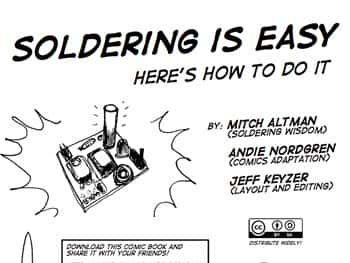
Guide to learning to solderWe love when we come across electronics info and guides that others are sharing freely – and especially those that encourage others to share their knowledge and work.

For example…here is a fully illustrated guide to learning how to solder which was done by the fine folks at http://mightyohm.com. They’ve created a super guide with all the basics covered as well as some interesting tips and tricks that can make your soldering experience a little better. This would be a great staple for some basic electronics classes.

To see the full soldering guide, click on the image above.

Thank you to the creators of this comic book: Mitch Altman, Andie Nordgren and Jeff Keyzer. Great work!

Solder Sucker for Desoldering – New product alert!

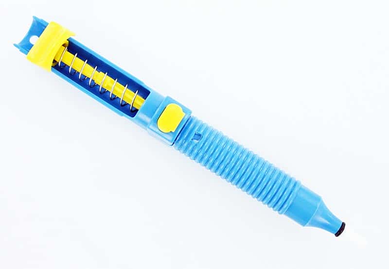
Solder Sucker

Solder Sucker

We’re always adding new electronic components, parts and supplies to our inventory. This week, one of our new products is a solder sucker, which is a ‘must have’ for anyone that works with electronics and solder.

Crafted in Germany by Amax, this solder sucker is a pump style solder remover. Use it on heated solder to remove the solder from your boards and components. It comes in the original manufacturer’s packaging with instructions for the use and care of your solder sucker.

Here are some basic desoldering instructions:
1. Heat your soldering iron. Push down on the plunger until it clicks to arm the soldering iron.
2. Clean your soldering tip. Place the soldering tip on the side of the old joint. Apply some fresh solder on the old joint to help the old solder soften.
3. Set the plunger on the solder sucker. Place the tip of the solder sucker on the old joint as close as possible to the soldering tip.
4. Release the plunger by pressing the button.
5. Repeat until much of the old solder is gone.
6. If any of the old solder is left in PCB holes, you can heat the old joint again and using the soldering tip on one side and a miniature flat screwdriver on the other, gently rock the joint back and forth lightly to loosen up the tiny leads on the components.
7. You may need to repeat this process again when there is a stubborn joint.
9. Remove your component carefully; taking care to not damage the board.

Desoldering – Why is it Necessary and How is it Done?

Soldered joints, if improperly done, may need to be ‘desoldered’ or the solder removed in order to resolder them. A poorly soldered joint can result in failure of the electrical circuit over a period of time. This can happen for a number of reasons. Low quality solder or failure to properly clean the surface before soldering or even lack of proper technique and corrosion of the joint due to leftover flux, movement (shake) of the joint before the solder has cooled may all cause a poor soldered joint.

There are other reasons you might need to desolder a joint. Desoldering and resoldering may also be required in order to replace a defective electronic component or if you are troubleshooting an electrical circuit.

One common method of desoldering is to use a desoldering pump which is a vacuum pump similar in operation to a bicycle pump in reverse. The spring loaded plunger breaks the solder and gets sucked away by the pump. Repeated operation of the pump may be required in order to completely desolder a joint, or you can also use the solder pump to take up the bulk of the flowing solder and finish up the job with solder wick. Either way works – the solder wick is more expenisve so you may want to use both if you have a large job. Be careful – the pump should be operated carefully so that no damage the PCB or the electronic components occurs.


A solder wick or braid is an alternative to desoldering pumps. Here the copper wick is placed over the joint and the solder is melted by means of soldering iron. The solder gradually flows into the wick and hence gets removed. The wick must be removed from the PCB before it cools down as otherwise it may damage the board.