Tag Archives: Guides

What is PID Control and How Does it Work?

We use control loops all the time. For instance, it is much easier to place an object on a tabletop with your eyes open than it is with the eyes closed. The eyes provide us with visual feedback to control the hand to place the object in the required position on the tabletop without error. In the same way, modern industrial controls regulate processes as a part of a control loop. The user sends a set point request to the controller, which then compares it to a measured feedback. The difference between the two forms the error and the controller tries to eliminate the error.

PID controls also work in the above manner, but also add a bit of mathematics. In fact, PID is an acronym for Proportional, Integral, and Derivative. The three terms allow the controller to adjust the rate at which it minimizes the error.

For instance, the proportional factor introduces a constant multiple KP. Therefore, the controller moves at a constant factor from its present position to the desired set point. If the present position is far from the desired set point, the error is large, keeping the speed of approach high. As the error decreases, the speed of approach reduces. This is similar to a car running at high speed when it is far from its destination, with the speed reducing as it nears its terminus. When error reduces to a certain level, the Integral term takes over.

The integral term controls the rate of change over a given interval based on the summation of error over time. Therefore, the rate of change is no longer linear but changes in a non-linear manner. The speed of approach reduces non-linearly as the error approaches zero, and just before the controller settles, the derivative term takes over.

The derivative term controls the rate of change of the error over a given interval. In fact, it corrects the controller’s position based on the last time the positional error was checked. In reality, the three terms do not work independently as above, but concurrently. The magnitude of error defines which among them affects the controller more than the others.

All three components of the PID controller create outputs based on the measured error of the process under regulation. For a properly operating control loop, any change in error caused by a process disturbance or set point change can be quickly eliminated by the combination of the P, I, and D factors.

Sometimes PID controllers use only the proportional term. However, a proportional-only loop works with only a sizable error. When the error becomes small, the output of the controller is too low to enable corrections. Therefore, even when the control loop has reached steady state, there is still some error. The steady state error will reduce by setting a high proportional factor. However, setting a very large proportional factor, which depends on the gain of the controller, leads to repeatedly overshooting the set point, resulting in oscillations and making the loop unstable. This leads to steady state error and this is called offset.

Raspberry Pi and Automated Greenhouse

Many people set up greenhouses to grow tropical plants that need plenty of warmth and moisture. Usually these areas are enclosed in steel bracings holding glass/plastic panels that allow sunlight in and prevent moisture from going out. Greenhouse owners control the temperature by opening panels to allow ventilation. In winter, maintaining temperature could be difficult without use of heaters. Manually controlling temperature and humidity could be a tedious task taking away from the actual task of attending to the plants.

Therefore, an environment management system is an excellent way of controlling the weather within the greenhouse. Asa Wilson and his wife used a Raspberry Pi (RBPi) as the main computer for the environment management system for their greenhouse. They set up their greenhouse in Colorado on the western slope of Pike’s Peak. This place is notorious for its strong winds, while the normal growing season is very short.

As their greenhouse is rather small, measuring 10 x 12 ft., Asa uses a single temperature and relative humidity sensor. For larger greenhouses, the temperature and humidity at different locations will need to be monitored for effective control. Based on the input from the sensors, the RBPi controls the exhaust fans placed at opposite corners at the base of the greenhouse. The speed of these exhaust fans can be varied through custom speed control boards. Vents on the roof allow air to be drawn in when the exhaust fans are rotating. For air circulation, Asa uses a large oscillating fan mounted near the roof. The speed of this fan is set manually, and the RBPi can turn it on and off.

The greenhouse roof has four vents. Earlier, each vent could be opened with a single arm. However, that allowed the vents to vibrate in the wind, and they would sometimes close up. Asa designed and used vent controllers with geared motors and housed them in 3-D printed cases. The new vent controllers have two arms to hold each vent panel firmly on both sides, and this prevents any oscillations.

Initially, Asa used the RS232 protocol to let the RBPi talk to all the custom controllers. However, noise generated by the different devices caused communication issues. This led Asa to change over to RS485 drivers, which uses differential mode of communication for driving the signals. This solved the noise issue.

Although this is only a beginning, Asa is pleased with the results of his greenhouse. He is now planning for additional work. He is planning to add twenty more temperature sensors in the growing area for sensing temperature of individual plants, and a thermal controller for monitoring the sensors. He also plans to add seven water valves that will allow fine control on the humidity within the greenhouse.

Other people have also built automated greenhouses. For instance, David Dorhout has an automated watering robot that potters around carrying a 30-gallon tank for watering plants that need watering. Instrument Tek also has a similar greenhouse to Asa’s with an Arduino based system. In addition to watering and fan control, this also controls heat and communicates remotely to a computer.

Cloud Storage and Alternatives

Ordinarily, every computer has some local memory storage capacity. Apart from the Random Access Memory or RAM, computers have either a magnetic hard disk drive (HDD) or a solid-state disk (SSD) to store programs and data even when power is shut off—RAM cannot hold information without power. The disk drive primarily stores the Operating System that runs the computer, other application programs, and the data these programs generate. Typically, such memory is limited and tied to a specific computer, meaning other computers cannot share it.

A user has two choices for adding more memory to a computer—he/she can either buy a bigger drive or add to the existing one, or he can use cloud storage. Various service providers offer remote memory storage, and the user has to pay a nominal rental amount for using a specific amount of cloud memory.

There are several advantages of using such remote memory. Most cloud storage services offer desktop folders where users can drag and drop files from their local storage to the cloud and vice versa. As accessing the cloud services requires Internet connection, the user can avail the cloud facilities from anywhere, while sharing it between several computers and users.

The user can use the cloud service as a back up for storing a second copy of their important information. In the event an emergency strikes and the user loses all or part of their data on their computer, accessing the cloud storage through the Internet can help to restore the stored information on the cloud. Therefore, cloud storage can act as a disaster recovery mechanism.

Compared to local memory storage, cloud services are much cheaper. Therefore, users can reduce their annual operating costs by using cloud services. Additionally, the user saves on power expenses, as cloud storage does not require the user to supply power that local memory storage would need.

However, cloud storage has its disadvantages. Dragging and dropping files to and from the cloud storage takes finite time on the Internet. This is because cloud storage services usually limit the bandwidth the user can avail for a specific rental charge. Power interruptions and or bad Internet connection during the transfer process can lead to corruption of data. Moreover, the user cannot access his/her data on the cloud storage unless there is an Internet connection available.

Storing data remotely also brings up the concerns of safety and privacy. As the remote memory is likely to be shared by other organizations, there is a possibility of data comingling.

Therefore, people prefer using private cloud services, which are more expensive, rather than using cheaper public cloud services. Private cloud services may also offer alternative payment plans, and these may be more convenient for users. Usually, the private cloud services have better software for running their services, and offer users greater confidence.

Another option private cloud services often offer is of encrypting the stored data. That means only the actual user can make use of their data, and others, even if they can access it, will see only garbage.

What is a Wireless Router?

Most of the electronic gadgets we use today are wireless. When they have to connect to the Internet, they do so through a device called a router, which may be a wired or a wireless one. Although wired routers were very common a few years back, wireless routers have overtaken them.

Routers, as their name suggests, direct a stream of data from one point to another or to multiple points. Usually, the source of data is the transmitting tower belonging to the broadband dealer. The connection from the tower to the router may be through a cable, a wire, or wireless. To redirect the traffic, the router may have a network of multiple Ethernet ports to which users may connect their PCs, or, as in the latest versions, it may transmit the data wirelessly. The only wire a truly wireless router will probably have is a cable to charge its internal battery.

Technically speaking, the wireless router is actually a two-way radio, receiving the signals from the tower and retransmitting them for other devices to receive. A SIM card inside the router identifies the device to the broadband company, helping it to keep track of the routers statistics. Modern wireless routers follow international wireless communication standards—the 802.11n being the latest, although there are several of the type 802.11b/g/n, meaning they conform to the earlier standards as well. Another differentiation between various routers is their operating speed, and the band on which they operate.

The international wireless communication standards define the speed at which routers operate. For instance, wireless routers of the type 802.11b are the slowest, with speeds reaching up to 11 Mbps. While those with the g suffix can deliver a maximum speed of 54 Mbps, those based on the 802.11n standard are the fastest, reaching up to 300 Mbps. However, a router can deliver data only as fast as the Internet connection allows. Therefore, even if it has a rating of n or 300 Mbps, it will perform at speeds of 100 Mbps at the most. Nonetheless, a fast wireless router can increase the speed of your network, and this allows PCs to interact faster, making them more productive.

International standards allow wireless communication on two bands—2.4 GHz and 5.0 GHz. Most wireless routers based on the 802.11b, g, and n standards use the 2.4 GHz band. These are the single band routers. However, the 802.11n standard allows wireless devices to operate on the 2.4 GHz or the 5.0 GHz band also. These are the dual-band routers, which can transmit in either of the two bands via a selection switch, or in some devices, they can operate in both frequencies at the same time.

A newer standard, 802.11a, allows wireless networking on the 5.0 GHz band, while also transmitting on the 2.4 GHz band used by the 802.11b, g, and n standards. These are also dual band wireless routers with two different types of radios that support connections on both 2.4 GHz and 5.0 GHz bands. The 5.0 GHz band offers better performance, lower interference, and more coverage.

Why do you need a Good Grounding?

Grounding is a safety measure for electrical and electronic systems whereby the user is protected from accidentally coming in contact with electrical hazards. For instance, refrigerators at home usually stand on rubber feet, even when operating from the AC outlet. Although electricity enters the refrigerator and runs through most of the electrical components within it, it has no connection to the outer metal body. Rather, the outer metal body of the refrigerator connects independently to a green grounding wire, which leads to the third pin (the thickest one) on the power plug.

If the outer metal body of the refrigerator was not grounded as above, and for some reason, electricity came in contact with the outer metal chassis such as from leakage, it would cause injury to anyone, if the person were to touch the refrigerator. Connecting the outer metal body to the grounding wire protects the person from being electrocuted, as electricity present on the metal body passes to the earth directly instead of through the person.

This is presuming the third pin on the power plug is connected to a good grounding arrangement outside the building. Typically, this arrangement is a ground rod, or a grounding electrode inserted into the soil. The arrangement works because the earth is a good conductor of electricity, and the overhead transformer that supplies power to the area, also has a grounding arrangement near it, which completes the circuit for the leakage current of the refrigerator. Therefore, a good grounding arrangement is essential for safety.

Apart from safety, most of the electronic equipment, such as computers, microwave ovens, LED lights, televisions, and more, need to be securely grounded to operate effectively. This is because most electronic equipment generate huge amounts of electrical noise that affect other equipment nearby. This can cause damage to an equipment, or cause it to work less effectively. Proper grounding helps to remove the unwanted noise, allowing all equipment to inter-operate more effectively.

Another advantage of a good grounding system is it helps protect against lightning. Lightning has high-voltage electricity with fast rise-times and causes large magnitude currents. A grounding system must present a low-resistance path for the high currents from a lightning strike to enter the earth, without causing damage to the building or equipment within.

Therefore, low resistance or low impedance of grounding is the key to protection from leakage of electricity, electrical noise, and lightning strikes. A good practice is to have all grounding connections as short and direct as possible, and connected with a heavy gauge wire, preferably made of copper. This ensures minimization of inductance and reduces the peak voltages induced.

The effectiveness of the grounding system in coupling the unwanted electricity to ground depends on a number of factors. This primarily includes the geometry of the ground electrode, the size of the conductors, the effective coupling into the soil, and the resistivity of the soil around the electrode.

Therefore, the basic requirements of any ground installation are to maximize the surface area of the electrode with the surrounding soil. This helps to lower the earth resistance and impedance.

Mica Capacitors : Why should I use them?

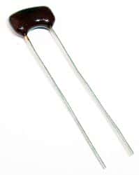
mica capacitorMica, a phyllosilicate, is a group of hydrous potassium/aluminum silicate material. It is a rock-forming mineral exhibiting a two-dimensional sheet or layer structure. That means it is possible to split mica into thin sheets. The biggest advantage of mica is the excellent stability of its electrical, chemical and mechanical properties. This property makes mica a suitable material for use as a dielectric when making highly stable and reliable capacitors. Silver-mica capacitors are useful at high frequencies, because of their low resistive and inductive losses and high stability over time.

Delved in India, Central Africa and South America, the most commonly used are the muscovite and phlogopite mica. While the first has superior electrical properties, the latter has a higher temperature resistance. Mica capacitors are expensive as the raw material composition has high variation, requiring inspection and sorting. Silver mica capacitors have sandwiched mica sheets coated or plated with silver on both sides. The assembly is then encased in epoxy to protect it from the environment.

Tolerance and Precision

Among all types of capacitors, silver mica capacitors offer the lowest tolerances, as low as +/-1%. In comparison, ceramic capacitors have tolerances going up to +/-20% and electrolytic capacitors can have more.

The design of a silver mica capacitor does not allow any air gaps inside. Additionally, the entire assembly is sealed hermetically from the environment. That allows the mica capacitor to retain its value over long periods. As the assembly is protected from the outside effects of air and humidity, the capacitance of a mica capacitor remains stable over a wide range of temperature, voltage and frequencies. The average temperature coefficient of mica capacitors is around 50 ppm/°C.

Losses

Mica capacitors have a high Q-factor. This comes from the low resistive and inductive losses exhibited by these capacitors. That makes them a suitable choice for use at high frequencies, but it comes at a price – silver mica capacitors are expensive.

It is difficult for manufacturers to make silver mica capacitors of larger capacitance value. Typically, this ranges from a few pF up to a few nF. However, they can stand high voltages and mica capacitors are usually rated for voltages between 100 and 1000 volts. Special mica capacitors are rated up to 10KV and these are mostly for use with RF transmitters.

Applications

You can use silver mica capacitors wherever the application requires low capacitances, high stability and low losses – especially in power RF circuits – requiring very high stability.

You can also use silver mica capacitors in high frequency tuned circuits such as oscillators and filters. Pulsed applications such as snubbers also use mica capacitors as they can withstand high voltages. If cost is an important factor along with tolerance and low losses, you can replace mica capacitors with class I ceramic capacitors. Ceramic capacitors are available at a fraction of the price of mica capacitors.

Mica capacitors are available as surface mount versions as well. This offers several benefits over radial or axial assemblies. By eliminating the leads, SMT designs offer a smaller device size that can be mounted directly to the PCB – resulting in a more compact design and greater mechanical stability.

Which Raspberry Pi Should I Use?

Which Raspberry Pi or RBPi you will use is getting more and more difficult to answer as the family keeps growing. It was simple and straightforward when the RBPi first launched – there was only one model. Since then, with four major models to choose from, things are more complicated. However, this versatile beast comes in different specifications and you should select the one most fitting your requirements. Among the models available, here is a summary to help you decide:

RBPi Zero

This is the latest addition to the family. Although it is ultra-cheap, the RBPi Zero is definitely a fully functional single board computer. Compared to the first model of family, the processor used in the RBPi Zero is more than 40% faster. However, purchasing this variant compels you to make major compromises.

To start with, you will need adapters to use the mini HDMI and micro USB ports on the device. As there is no on-board Ethernet port, you need to use the single USB port. Although you can expand its functionality by adding a powered USB hub, the additions begin to detract from the major selling point of the Zero – its tiny footprint.

If the application does not require a fair amount of connectivity, is low-powered and for single-use, you may consider using the RBPi Zero.

RBPi Model A+

Although a full-sized version, this model also lacks the Ethernet port and has only one USB port. Moreover, it has only 256GB RAM that goes with the 700MHz processor. The price and lack of power makes it difficult to recommend the RBPi Model A+ for any application other than for specific ones.

RBPi Model B+

If performance is not a criteria and price is the only consideration, then the RBPi Model B is hard to beat. The model offers good connectivity as it has on-board Ethernet, four USB ports and a full sized HDMI connector. That makes the RBPi Model B+ more versatile than either the Model A+ or the RBPi Zero.

You can use it for any project that requires good connectivity, less than top-notch performance, and low power.

RBPi Model 2

This is the top-of-the-line model in the family and a surprisingly capable beast. With an updated chipset, a quad-core processor and 1GB RAM, the RBPi Model 2 makes a major difference in the large variety of Single Board Computers available in the market.

You can use the RBPi Model 2 as a media server for your network or use it for tasks of more intensive nature such as running a home surveillance system or playing games. It also allows you to explore platforms other than Linux – you can run the IoT version of Windows 10.

Even though the total power consumed by the RBPi Model 2 is below 1W, it uses significantly more power as compared to its predecessors. For example, RBPi Model 2 consumes more than 33% power drawn in by the RBPi Model B+ and five times more power than what the RBPi Zero consumes. Use the RBPi Model 2 for anything where you need good performance.

Check our other guides for information on Model 3.

Some of the Best Raspberry Pi Add-Ons

To most people, the Raspberry Pi or the RBPi Single Board Computer is only a cheap desktop. That is because by the time you have added a monitor, a keyboard, a mouse and the SD card, it would have cost as much as a cheap laptop and would still be a lot less powerful.

However, the real innovation of the RBPi lies not in its cost, but in its form factor. You can run the tiny RBPi on a few batteries or solar cells and use its exposed General Purpose Input and Output pins. This trio of combinations does not have any precedents in computing, at least not in the price range of the RBPi.

Being a new type of device, the RBPi is a lot easier to understand with some of the readily available components that connect to it to enable some function or to add some feature.

Most of these add-on components are not from large companies, but developed by hobbyists who saw the need for and filled it. One of these add-on components is the multi-purpose LED display Pi Lite. This is a simple board full of LEDs allowing people to use the RBPi to turn them on or off individually. This has made the RBPi SBC different from the regular PC and forced people to think differently for using it in its particular niche.

Pi Lite has 126 red LEDs, with a white LED version on its way. You plug the board into the GPIO pins on the RBPi. Pi Lite nearly covers the main RBPi board and has about the same form factor. Of course, you need a little configuration to enable the board to use the RBPi serial port, but that is well documented.

You send commands to the Pi Lite via a minicom terminal. Once connected over the serial port, anything sent over will scroll across in beautiful red light. Not only can you send text, you can also send commands preceded by three-dollar signs. You can turn all pixels on or off, display horizontal and vertical graphs and manipulate individual pixels.

You can improve the connectivity of your RBPi by expanding its ports. As the GPIO pins are exposed, any circuitry can be added to the RBPi. That may cause accidents and fry your RBPi very easily. Although there are several add-on boards that provide access and protection to the RBPI GPIOs, Quick2Wire has a board that uses the I2C and SPI features of the RBPi.

These are the Inter-Integrated Circuit and Serial Peripheral Interface and the board comes in two parts. The main board provides the I2C and SPI ports, adds protection for the RBPi and voltage selectors. Additional boards provide more GPIO ports including analog inputs and outputs that RBPi lacks. You can daisy-chain the boards to allow even more ports to be added to the RBPi.

To control the ports, you need to program the board with the Python programming language. For this, you may have to install the python3-setuptools package. You can find additional details of the above two add-on boards in openmicros.org and Quick2Wire.com.

What Are Diacs And Triacs Used For?

When you switch on your fan or light, chances are you also have a dimmer controller to control the speed of the fan or the intensity of the incandescent or LED light. Typically, dimmers are useful only where alternating currents are used, because they have components that allow only part of the waveform to reach the appliance. That means the appliance receives only part of the energy supplied and hence runs slower or glows dimly. Dimmers accomplish this AC waveform chopping or phase control with the help of two active components – a diac and a triac.

A diac is a bi-directional diode, equivalent to two zener diodes connected back-to-back. The diac is designed to break over at a specific voltage. When the voltage applied (in either polarity) to the diac is less than this break over voltage, the device continues in a high resistance state allowing only a minor leakage current.

As the applied voltage crosses the break over voltage (in either polarity), the diac starts conducting with a negative characteristic. That means, as break over occurs, the current flow increases and there is a corresponding voltage drop across the device. According to Ohm’s Law, an increase in current typically leads to a larger voltage drop, provided the resistance remains constant. However, since the diac shows a drop in voltage with increased current at break over, its resistance must have decreased. This is the reason for stating a diac exhibits negative resistance at break over.

The triac operates similar to two thyristors connected in reverse parallel but with their gates in common. Therefore, a triac can conduct in both directions when a voltage of either polarity is present across it and it has been triggered on by its gate terminal. The polarity of the gate pulse is immaterial for initiating conduction of a triac.

By controlling the gate pulse to occur at a specific position in the voltage waveform applied to the triac, it can be made to conduct for only a part of the entire cycle. This allows delivery of a fraction of the voltage to the appliance.

In a dimmer circuit, a diac is used to trigger the triac. Typically, a capacitor is allowed to charge via a variable resistance from the supplied AC voltage. As the capacitor charges through the resistor, the voltage on the capacitor rises until it reaches the breakdown voltage of the diac. The diac then conducts and triggers the triac, which, in turn, applies the remaining voltage of the cycle to the load/appliance. As the supply AC voltage crosses over, the triac switches off automatically, until again triggered by the diac.

If the resistance is large, the capacitor charges slowly and voltage on the capacitor takes more time to reach the breakdown voltage of the diac. That triggers the triac later in the waveform, preventing a major part of the voltage waveform from reaching the appliance. If the capacitor is allowed to charge faster, by keeping the resistance smaller, the triac triggers early in the cycle, and more voltage can reach the load.

What is a brushless DC motor?

Most electrical appliances have an electric motor that rotates to displace an object from its initial position. Various motors are available in the market such as servomotors, induction motors, stepper motors, DC motors (both brushless and brushed), etc. The choice of a motor depends on the requirements of an application. Most new designs favor brushless DC motors, also referred to as BLDC motors.

The working principle of brushless DC motors is similar to that of brushed DC motors, but their construction is very close to that of AC motors. Like all motors, a brushless DC motor too has a stator and a rotor as its major parts.

The stator of a brushless DC motor, similar to the stator of an induction AC motor, is made up of laminated CRGO steel sheets stacked up to carry the windings. The stator windings follow one of two patterns, star and delta. Motors with stators wound in star pattern produce high torque at low RPM compared to motors whose stators are wound in a delta pattern. For motors required to run at very high speeds, the stator core has no slots, as this lowers the winding inductance.

Lack of slots in the lamination stack means the stator has no teeth, which reduces the cogging torque. Teeth in the stator align with the permanent magnets in the rotor, holding the rotor in a stationary position. When starting to move, additional torque, known as the cogging torque is required to make the rotor break free. However, slotless cores are more expensive as a larger air gap is necessary and that means more winding to compensate.

A typical brushless DC motor has its rotor made out of permanent magnets. The number of poles in the rotor depends on the requirements of the application, as more number of poles gives better torque. However, this reduces the maximum possible speed. Torque produced in a brushless DC motor also depends on the flux density of the material of the permanent magnet; higher flux density material produces higher torque.

Brushless DC motors are popular due to several advantages they offer over other types of motors. Compared to brushed type of motors, a BLDC motor produces higher torque because it has no brushes where power may be lost. Lack of brushes also means higher operating life and lower maintenance. Compared to AC motors, the rotor construction is simpler as it has no windings.

The cost to performance ratio of brushless DC motors is the lowest among all the types of motors available. One reason for this is the stator of a BLDC motor is on its outer periphery, which makes it dissipate a larger amount of heat. Additionally, commutation of brushless DC motors is simpler through electronic switches. That makes it easier to control the speed of BLDC motors.

Whether you are looking at single-speed, adjustable speed, position control or low-noise applications, brushless DC motors are the clear winners over all other types. As they are easier to control, maintaining speed of brushless DC motors is simpler with variations in load. A brushless DC motor generates very low amounts of EMI and audible noise.