Tag Archives: electronic components

Opening Up and Tearing Down an IPOD Shuffle

Opening up and tearing down an IPOD Shuffle to see what’s inside…

The 3rd Generation of the IPOD Shuffle is a wonder of technology….1000 songs stored in an aluminum case smaller than a disposable lighter.

Did you ever wonder what electronic components make up the guts of an IPOD Shuffle?

You might be surprised at what goes into the circuitry of the IPOD Shuffle. In descending order by percentage of cost, the main components are:

logic, memory, metals, rechargeable materials, connectors, PCB, crystal, misc, capacitors, transistors, analog, diodes, magnetic, and plastics.

Here’s a partial breakdown by number of electronic components:

Capacitors – 65+
Resistors – 50+
Diodes – 4+

Pretty amazing what goes into equipment that measures only 45.2mm x 17.5mm x 7.8mm when fully assembled! This is possible because the components are extremely small surface mount components.

If you look at the cost breakdown by component family, it’s just as revealing. Naturally, the largest share is for memory in the form of IC’s. Over 70% (about $12.00 worth) is for logic and memory.

Available Methods of Marking Semiconductors

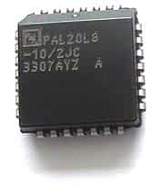
Semiconductor Markings – Available Methods

Traditionally, most components have two or three lines of identifying marks plus a company logo. Over time, the manufacturer codes have become more involved to incorporate a component’s identification plus the complete history of the process. Early on, it was the military applications that required very specific markings and identification processes. Current package markings are a by-product of those military requirements.

When a semiconductor is clearly identified, there is less room for error in the production process. Reducing errors when a component is in use for production saves time. There is also less product waste and the production process becomes more streamlined.

As the size of electronic components has decreased, the available space that manufacturers have to mark each piece has also decreased. The technology required to complete this task has become increasingly more complex.

The chief reason for the more complex codes stems from the demands of the end users. They need to have complete traceability of the product; from the history of the production cycle including the date and location of manufacture to the exact lot code. Possession of this information is critical to the end user in the event of a recall or defective components.

There are four primary methods to marking components in current use. Use of the various methods depend on the size, the type and the environment of the component production.

The methods are:
-Ink marking
-Electrolytic marking
-Pad printing
-Laser marking

In ink marking, inkjet printers are used. The technology is called ‘drop-on-demand’ which means that the flow of ink is controlled to create a pattern of ink droplets to form an image marking.

Electrolytic marking employs low voltage electric current with a stencil. The top layer of the package is etched by electricity flowing from the marking head, assisted by an electrolyte chemical. The process takes approximately 2-3 seconds to complete.

Pad printing is the most traditional of all the processes. A steel plate is etched with the image of the imprint. The ink is transferred to the plate which then is applied with pressure to the surface of the electronic component.

Laser marking is the most recent development in the marking process. It provides the greatest flexibility in the size, timing and complexity of the markings. The laser process is also the fastest method to mark electronic components; it is not uncommon for this process to print up to 300 characters per second. An additional benefit of using laser printing is the ability to produce a clean mark on many irregular surfaces.

No matter which method has been used to mark the semiconductors you use, you can be sure that much thought has been put into the decision.

How To Clean Potentiometers On Your Audio Equipment

How to Clean the Potentiometers on Your Audio Equipment

If you have a dirty potentiometer, you probably will find out about it from the scratchy sounds your equipment will make when you adjust the volume control.

Here’s a simple and safe method to rid yourself of that noise:

-Unplug your equipment
-Remove the cover from the knob
-Carefully use contact spray on the shaft of the potentiometer
-Replace the knob
-Plug your equipment back in and turn it on
-Rotate the knob from one end of the range to the other.

Did that work? It should have – but if you still hear the scratchy noise, you can move onto this step:

-After unplugging the equipment again, remove the potentiometer from the housing and use the contact spray at the base. Before you put it back into the housing, rotate the shaft to be sure that it’s moving cleanly.

If you still hear noise, it might be time to replace the potentiometer. Before you cut the wires, it is recommended that you snap a couple of pictures of the previous installation including all wires leading to the potentiometer. This will assist you greatly when it’s time to connect the new pot.

Once you obtain the correct pot to install, you will need to use solder and a soldering gun to reconnect the wire leads from the potentiometer to the equipment.

Hopefully it won’t be necessary to replace the potentiometer. Most often, a spray is all it takes to rid yourself of the noisy potentiometer.

How Do You Store Your Electronic Components?

Storing and retrieving a large number of electronic components like capacitors, resistors, LEDs, transistors, diodes, ICs etc. can be a daunting task not only because they are tiny but also because extreme temperature and humidity can deteriorate their performance. They also need careful handling as they are fragile and the tips can break easily.

In addition, electronic components need to be protected against static electricity.

To keep static electricity from damaging your sensitive electronic components, we recommend that you use sheets of anti-static foam. These foam sheets are easily cut to size to fit your storage containers.

A sheet of pink anti-static foam

A sheet of pink anti-static foam

There are a variety of container options to store electronic components safely. A range of molded ABS plastic boxes that can be side locked and stacked either vertically or horizontally are available. Each drawer has a number of compartments and can be labeled for easy identification. The various electronic components like resistors, capacitors etc need to be sorted and stored in these compartments in logical fashion. The drawers are easy to slide and can be pulled out / pushed in without much effort.

Ever wonder how the large electronic distributors store and retrieve their components? Automatic storage and retrieval systems make the job of storing and retrieving large numbers of electronic components easy and efficient. A typical construction has a vertical carousel in which a number of cameras are mounted on an endless chain activated by geared motors. The shelves are capable of rotating in either direction in a vertical plane. An electronic keypad facilitates calling the numbered carrier and bin / compartment. The system is equipped to store information about the location of code numbered electronic components in its memory. It can also be linked to a central computer for sharing of information for inventory control purposes. These automatic systems enable fast access of electronic components, instant stock update and save floor space, time, manpower and paper work involved in conventional storage systems.

Desoldering – Why is it Necessary and How is it Done?

Soldered joints, if improperly done, may need to be ‘desoldered’ or the solder removed in order to resolder them. A poorly soldered joint can result in failure of the electrical circuit over a period of time. This can happen for a number of reasons. Low quality solder or failure to properly clean the surface before soldering or even lack of proper technique and corrosion of the joint due to leftover flux, movement (shake) of the joint before the solder has cooled may all cause a poor soldered joint.

There are other reasons you might need to desolder a joint. Desoldering and resoldering may also be required in order to replace a defective electronic component or if you are troubleshooting an electrical circuit.

One common method of desoldering is to use a desoldering pump which is a vacuum pump similar in operation to a bicycle pump in reverse. The spring loaded plunger breaks the solder and gets sucked away by the pump. Repeated operation of the pump may be required in order to completely desolder a joint, or you can also use the solder pump to take up the bulk of the flowing solder and finish up the job with solder wick. Either way works – the solder wick is more expenisve so you may want to use both if you have a large job. Be careful – the pump should be operated carefully so that no damage the PCB or the electronic components occurs.


A solder wick or braid is an alternative to desoldering pumps. Here the copper wick is placed over the joint and the solder is melted by means of soldering iron. The solder gradually flows into the wick and hence gets removed. The wick must be removed from the PCB before it cools down as otherwise it may damage the board.

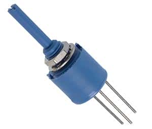
The Basics of Potentiometers

Potentiometer Basics

A potentiometer is a manually variable resistor. It has 3 terminals, one of which is connected to ground, the second to a current source and the third to a sliding contact that runs along a strip of resistor. The varying resistance is used to control other parameter like volume. Potentiometers are widely used electronic components used in volume control, brightness control etc. though recently they are being replaced by digital control circuits.

A potentiometer can regulate the amount of current flow in a circuit. In this case, the maximum current flow is limited by the resistivity of the variable resistor. The variable resistor can be in the form of a linear strip or a circular strip. In a linear potentiometer, the cross section of the resistor is constant and the resistance varies directly with the length of the resistor. In a logarithmic potentiometer, the resistor tapers from one end to the other and the cross section varies likewise. The variation of current flow is logarithmic in this case and is used in audio amplifiers.

A digital potentiometer is digital equivalent of variable resistor potentiometer. It is a digitally controlled electronic component with built in IC or a digital to analog converter. It is widely used in instrumentation amplifiers. It has limitation of being restricted to currents of a few milli amperes and voltage in the 0 to 5V range.
Relays

Relays

Relays are electronic or electromechanical switches that operate under the control of an external circuit.

Originally when first invented in 1835, electromechanical relays consisted of an electromagnet and a set of contacts. When the electromagnet was energized, it closed the contact by attracting a lever held by a spring. When no current is flowing through the circuit, the electromagnet got demagnetized and the spring pulled back the lever and the circuit was left open. This type of relay was widely used in devices such as calling bells.

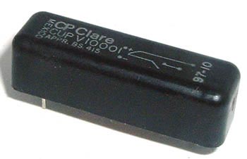
CP Clare Relay

CP Clare Relay

A special type of relay is a reed relay in which the contacts are enclosed in vacuum tubes in order to protect them from atmospheric corrosion. The operation is otherwise similar to electromechanical relays.

More recently solid state relays have come into vogue. Solid state relays are electronic components similar in function to electromechanical relays. Though initially used for low current applications, these relays are available nowadays for handling currents up to 1200A. They consist of circuits involving transistors and resistors. They have no moving parts and hence no wear out and operate much faster than electromechanical relays.

Relays are widely used in many electric and electronic control applications like overload protection of motors (circuit breakers), temperature / pressure regulators in refrigerators, railway signaling, power systems, starter for automobiles, machine tools etc. As electronic components relays are used in modems and audio amplifiers etc. Modern relays are activated by microprocessor or programmable logic controllers that have the operation logic built in.

What Happens to Old Electronic Components and Boards?

We came across this blog post the other day and thought it was worth bringing here.

Here’s an excerpt:

Yesterday I had the opportunity to shoot video in a facility that is the largest company in America that recycles the glass from electronics and computers. The men who own this company, built the machines that separate and break up the glass, themselves.

Electronic products and computers are torn apart. The plastics are sold to one vendor while the electronics and circuit boards are sold to another. The glass fragments are then shipped to companies that melt it down and produce new glass.

I was impressed by how much of the material is able to find new life, rather than to be dumped into a landfill where it would simply sit for all time.

I hope that he’ll update his blog when this segment is aired – I’d love to see the whole process!

How to Use an Analog Multimeter

How to use an Analog Multimeter
…it’s simpler than you think!

Multimeters are inexpensive and easy to operate, making them very popular. They are very commonly used as devices for electronics circuits testing. Multimeters are categorized into two different types – analog and digital. While the internal circuitry and operation of both are very different, their usage is more or less similar.

Analog multimeters have been in use for a long time and are very flexible in their operation. An analog multimeter can be used for testing a number of electronic components and parameters such as resistance, voltage, current, to name a few.

If you are using an analog multimeter, the first step is to switch the multimeter on. Next, the probes (or the leads) need to be inserted in to their correct positions. There can be a number of connections that can be made, and depending upon what is to be connected, the right positions should be determined. Care should be taken to not insert the leads in to a low current position, if high current is to be measured.

Next step is to set the center switch or knob to the required measurement type and the proper range. The range selected should be higher than the anticipated value. If the value is not known then the multimeter should be set to maximum and the range accordingly decreased afterwards. This ensures that the meter does not get overloaded. The range should be optimized for getting the best reading possible.

Once the reading has been taken, it is good practice to place the multimeter probes in to the voltage measurements sockets with the range set to maximum voltage. This ensures that even if the multimeter is accidentally connected, there is no damage to the multimeter or other electronic components of the circuit. Or if the reading is complete, then the multimeter can be switched off.

What is Transistor-Transistor-Logic – TTL?

TTL Transistor-Transistor-Logic

TTL Transistor-Transistor-Logic


TTL or Transistor-Transistor Logic is a type of digital circuit that is made from BJT or bipolar junction transistor along with resistors. Both the amplifying function and the logic gating function are carried out through transistors, thus the name transistor-transistor logic.

TTL is used for many applications like industrial controls, computers consumer electronics, test equipment, synthesizers and more. The TTL designation is also used in some places to imply ‘compatible logic levels’ even if they are not directly associated with transistor transistor logic circuits.

James Buie invented the Transistor Transistor Logic in 1961 and the first Transistor-Transistor Logic devices were made in 1963 in Sylvania. These devices were called the “Sylvania Universal High-Level Logic family” and were used within controls for the US Phoenix missile. In 1964 Texas Instruments produced ICs of 5400 series and later on, the 7400 series which made the Transistor-transistor Logic devices popular amongst electronic system designers. The 7400 series went on to become the industry standard. Many companies like AMD, Motorola, Intel, Fairchild, Siemens, National Semiconductor made compatible parts.

The TTL circuits were low cost which made them highly practical for using digital techniques in tasks which were earlier done through analog methods. One of the first computers that was built, in 1971, made use of the transistor transistor logic instead of a microprocessor chip which at that point of time was not available. With time incremental improvements in power consumption and speed were made, and the last popular series was the 74AS/ALS Advanced Schottky was made available in 1985.