Tag Archives: electronic components

What is a wind turbine?

A wind turbine is a rotary device that draws energy from the wind. This is different from a windmill, which draws energy from the wind but that energy is directly converted into mechanical energy used by some sort of machinery. Wind turbines are converted into raw electricity.

There are two main types, horizontal and vertical axis, of which the horizontal axis is more common. What are the differences between these two? Horizontal-axis turbines have the main rotor shaft and generator at the top of the tower. Horizontal axes must be pointed into the wind in order for them to work properly. However, the structure of the blades facing the wind also gives them a great angle of attack, which is the angle at which they have contact with the wind. This insures that the blades will be very efficient when converting wind to energy. Vertical-axis turbines are basically the same, except the axis is vertical, and they have the advantage of not having to face the wind.

Wind turbines are made up of three main components, the rotor component, generator component, and structural support component. The rotor component makes up about 20% of the cost, and consists of the blades. The generator component makes up 34% of the cost, and consists of the electrical generator, the control electronics, and usually a gearbox component for converting the low speed incoming rotation to high speed rotation which is better for generating electricity. Finally the structural support component makes up about 15% of the cost and consists of tower and rotor yaw mechanism.

Installing wind turbines can be a great way to save money on your electrical bills and create your own energy. They can be bought pretty inexpensively or you can even build your own and get the supplies to do it for even cheaper. If you are interested in building a basic wind turbine to see how it works, you should buy an educational wind turbine kit to get you started.

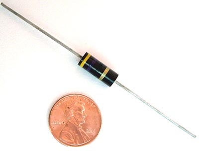
Application information for Allen Bradley resistors

Allen Bradley resistors are one of the best sellers on the West Florida Components web site with good reason.

The following information has been compiled to aid in the everyday selection and application of Allen-Bradley hot molded resistors. The statements should be helpful in evaluating the use of all types of AB hot molded resistors in broad general terms, and are not to be interpreted to be precise or exact.

A comprehensive list is made of the standard normal resistance values in their available tolerance categories, the rated continuous working voltages for all hot molded types, the part numbers, and color codes – all information provided for all values from 1 ohm to 100M ohm, taking into account the available range of values for each type (as of 1985).

Allen Bradley Resistors

Allen Bradley Resistors

1 – Low value resistors exhibit less change due to humidity, temperature and voltage than high value resistors.

2 – Resistance changes due to increase in moisture content are always positive.

3 – Resistance changes due to humidity are temporary, and, in the case of Allen Bradley resistors, are reversible.

4 – Change of resistance which has occurred due to humidity may be essentially eliminated by conditioning the resistor at 100°C or by dry storage.

5 – The effects of humidity may be minimized by operating the resistor with as little as 1/10 rated wattage load.

6 – Resistance change due to load life is permanent and usually ultimately negative.

7 – Resistance change due to load life can be minimized 1% – 2% in many thousands of hours by 50% derating period. The same result can be attained by limiting the maximum operation surface temperature of the resistor underload to 100°C. Permanent resistance changes as a result of storage of temperatures below 100°C are negligible, even for extended time periods.

8 – Resistance change due to soldering is positive and may be permanent if the resistor has excessive moisture present in its body. It can be greatly minimized if resistors are dry at the time of soldering.

9 – The temperature characteristics of Allen Bradley resistors is positive above +80 and below -10.

10 – The temperature characteristics of Allen Bradley resistors is negligible from -10°C to +80°C.

11 – The voltage characteristic (negative) and the temperature characteristic (positive) of Allen Bradley resistors tend to cancel one another in an Allen Bradley resistor in an average operating conditions, where both significant voltage and elevated temperature are present.

12- The heat sink to which a resistor is connected affects its rating. Resistors operated in multiple should be derated unless adequate heatsinks are provided.

13 – The quality and reliability of Allen Bradley resistors is the same for, and independent of, any resistance tolerances shown on the resistor.

14 – Years of accumulated experience have shown that Allen Bradley hot molded resistors are unequaled for uniformity, predictable for performance, appearance, and freedom from catastrophic failure. Allen Bradley resistors are made by an exclusive hot molding process on automatic machines developed, built, and used only by Allen Bradley. There is such complete uniformity from one resistor to the next, million after million, and long term in-circuit performance can be predicted with usable accuracy. When used according to published ratings and recommendations, Allen Bradley hot molded fixed resistors will not open circuit nor exhibit erratic changes of resistance value. They are probably the most reliable of all electronic components.

This information was taken in part from the Allen-Bradley corporation reference book dated 1985.

Make a coin battery – great electronics project for kids!

What better way to illustrate how to build a basic electronic connection than to use coins to build a battery?

Here’s what you need:

Quarter

Quarter

quarters or dimes
aluminum foil
blotter paper (see below)
salt
cider vinegar
wire (short length of both black and red wire – ~16 gauge)
1 LED (any through hole LED)
scissors
pen or marker
voltmeter (optional)

~~~~~~~~~~~~~~~~~~~~~~~~~~~~~~~

Trace the coins on the aluminum foil and blotter paper. Cut out 10 of each so that you have 10 circles of aluminum foil and 10 circles of blotter paper.

(Blotter paper can be found in the art store or the art section of your local craft store. You can also find blotter paper in the cosmetics department. If you can’t locate blotter paper, then you can also try using thick paper towels.)

Mix a small amount (1/4 cup) of vinegar with some salt. Stir the salt until dissolved. If the salt can not dissolve, then you’ve added too much. Add some additional vinegar and stir. Soak the circles of blotter paper in the vinegar and salt mixture.

Stack the foil, blotter paper and coins as shown in the video. It is important that the foil not touch the other layers. Let the ‘battery’ stand for about 15 minutes to develop a charge.

Connect each lead of the LED to a short piece of wire; the black wire connects to the negative lead and the red wire is attached to the positive lead on the LED. Place the exposed end of negative wire on the bottom of the ‘battery’ touching the foil, and the end of the positive wire to the quarter on top of the stack.

Optional: Use the voltmeter to measure how many volts are generated by the battery. A battery with 6 or more cells should be able to light up a standard LED with no problem!

OPA111BM and other hard to find parts

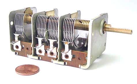
“I was so happy to find that you had Burr Brown OPA111BM in stock!” or “I’ve been looking for that Air Variable Capacitor for months! Can you get more of them?” We get these comments a lot from our customers.Air Variable Capacitors

West Florida Components started out selling surplus electronics before selling both obsolete and new-from-factory parts, and we made a name for ourselves by sourcing hard to get and out of production parts.

Over the years, we’ve kept looking for the surplus parts because our customers need them. Do you have a part that you can’t locate? Send us the part number and we’ll put it on our list of parts we’re actively looking for. We have an extensive list of suppliers and will be happy to look for you.

Converting dimensions from fractions to metric to decimal

We Americans are so used to seeing decimals or fractions for measurements that it’s not been easy for us to adapt to the metric system. Unfortunately, the industry standard sizes of most electronic components are provided in datasheets and descriptions as metric equivalents.

Need to convert a fraction or decimal to the metric system easily? Here is a decimal to fraction to millimeter conversion chart that will make that task easy for you. If you want to convert a number more precisely, use this link to jump to an online metric conversion calculator.

Of course, you can just use standard fractions, but it’s hard to find a T1 3/4 LED when you’re looking for it as a 0.19685 inches LED.

Screw-on rubber feet – newly expanded product line!

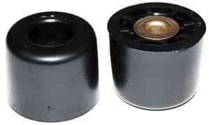
recessed bumpersWe’re listening! You requested a bigger selection, we got them! West Florida Components has now expanded their line of recessed bumpers. Recessed bumpers are also known as screw-on rubber feet and cabinet feet.

The rubber feet can be used in a variety of applications from electronic equipment to woodworking or carpentry and furniture. Where ever you require a rubber foot with a screw, these new rubber feet can be used. Check the specs on each foot for the sizes, recommended screw size and weight rating for each foot.

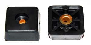
West Florida Components now carries 11 different sizes and shapes – including the popular square feet and the traditional round feet. Both shapes accept different screw sizes and rivets because of the plated steel support bushings included in the recessed area of each foot.

All the cabinet feet are manufactured from thermoplastic rubber which provides excellent shock absorbingsquare cabinet feet qualities and traction as well as being a non-marking material. Thermoplastic rubber is traditionally molded from Monsanto Santoprene®. Santoprene® is a thermoplastic rubber designed to offer chemical resistance equivalent to neoprene and is resistant to a wide variety of solvents and chemicals.

How to Make Your Own LEDS? Whooooooooa

I found this how-to today on the great Popular Science web site.

Now that I’ve read through the article – I am amazed that I’ve never seen these instructions written up before.

Theodore Gray, who authors their popular “Gray Matter” column, gives the full scoop on the basic materials used to construct LEDS and provides the basic instructions needed to see just how LEDS work.

OK, it is not so easy to find some synthetic silicon carbide (carborundum) laying around, but surely everyone could get their hands on some sandpaper, needles, a 9V battery and a snap. Follow his instructions, and VOILA…you’ve recreated the basic principles behind the creation of LEDS.

LED Basics: How to tell which lead is positive or negative

Here are more questions we get asked a lot:
What is the positive (or negative) lead on an LED? How do you determine the polarity of an LED?

If you are talking about through hole LEDS, in most cases it’s pretty easy to determine the polarity.

Through Hole LED

Through Hole LED

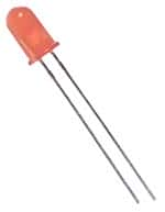
If the LED has two leads, one longer than the other,the longer lead is the postive (also known as the anode) lead.

If the LED has two leads with leads that are equal in length, you can look at the metal plate inside the LED. The smaller plate indicates the positive (anode) lead; the larger plate belongs to the negative (cathode) lead. Unfortunately, some jumbo LEDS have the plates reversed so this is not a fool-proof method.

If the LED has a flat area (on the plastic housing), the lead adjacent to the flat area is the negative (cathode) lead.

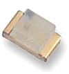
It’s a little bit harder to determine the polarity with Surface Mount LEDS. Some are marked with a (-) to indicate the negative lead, but often, they are not. The single best way to determine the polarity is through the use a multimeter.

Surface Mount LED

Surface Mount LED

Set the multimeter to the diode/continuity setting. Usually,the multimeter will supply enough current into the LED which will just barely light it up. The black (common) lead on the multimeter indicates the negative (cathode) lead, and the red indicates the positive or anode side.

Of course, if you can find the datasheet for your LED, the pinout, along with all the other specs will be readily available on the datasheet.

The Titan – Newest (and biggest) Vacuum Tube Amp from Steve

Just in from our friend Steve W. in Canada (who constructs the most amazing vacuum tube amplifiers)…

The best way to describe this next amplifier is it’s a Titan. It has to be the biggest, baddest, heaviest and most powerful amplifier I’ve made to date! Weighing in at just under 60 lbs. this push-pull-parallel EL-34 / 6L6 is conservatively rated at 110 watts per channel using EL-34 tubes. Capable of driving 4 or 8 ohm speakers via a switch on the back panel, this amp is a tube roller’s dream.

Simply by plugging in which rectifier tubes you want to use, be it a pair of 5Y3’s, 5R4’s, 5U4’s or even 5AR4’s you can match the correct plate voltage with what ever power tubes you choose, be it a set of 6V6’s, 6L6’s, 5881’s Kt-66’s, Kt-77’s, EL-34’s, or even 7591’s.

You also have the choice of running the amp in push-pull instead of push-pull-parallel simply by not installing the front four power tubes and switching off one of the two rectifier tubes via a switch located on the right hand side of the chassis. The signal and phase-inverter pre amp tubes used are my favourite large dual triodes 6SN7’s.

Now, about the transformers, seeing that this amplifier has to drive thirteen tubes, I thought it only made sense to use a separate filament power transformer. The transformer right next to the larger power transformer is the 20 amp filament transformer. By doing this, I’ve removed the heater load off of the main power transformer which now only has to supply the high voltages the amp needs.

Along with a hefty octet of 470 mfd 400 volt capacitors bought from West Florida Components, there is more than enough capacitance to keep this amp in the black during those high current moments when the music demands it.

By sharing the load this way, the main power transformer will not be taxed nearly as much. The output transformers are massive Hammonds that can easily handle the wattage this amp delivers.

You will notice a volume control knob located right smack in the middle of the mirror in front of the amp that’s surrounded in pure copper foil, and that is because this is a fully integrated power amp with a line stage pre amplifier built into it. That means you do not need to buy a separate pre amplifier. You only need to plug in your CD player, satellite, MP3, I-pod, or what ever type of line stage device you like to use, directly into the amplifier.

There are two benefits to an integrated amp, one, you don’t have to go out and spend money on a separate pre amp, and two, you are amplifying completely with tubes throughout the whole amplifying process from pre amp to power amp, and that makes it sound better, way better!

Once again – amazing job, Steve! Thanks for sharing this with our readers.

Tantalum Capacitor Industry Needs New Resources

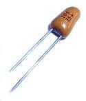
Tantalum Capacitor

Tantalum Capacitor

As the demand for tantalum has recorded 5% growth every year, the supply of tantalite has decreased setting up the electronic components industry with a possible shortage.

Tantalite, which is the key component of tantalum used to make tantalum capacitors, is mined primarily in three countries: Australia, Mozambique and Canada. Companies in those countries reduced or suspended production as the economy tanked in 2008 and consumer spending fell.

Recently, most production of tantalum has been taking place in Brazil and Africa but with the previous production facilities not producing the tantalum, a shortage through 2012 is possible.

What does that mean to consumers and companies that need tantalum capacitors?

Increased demand will push prices higher on current stock….and if current supplies are depleted, a shortage like the one that occurred in 2000 may occur pushing up prices even further.

Tantalum capacitors have grown in popularity for many reasons. To start with, tantalum capacitors have a larger volumetric efficiency when compared  to other types of capacitors. To illustrate this point, a 10uF tantalum can be used in place of a 100uF aluminum capacitor.

In addition, tantalum capacitors are able to be inserted on circuit boards easily. When you couple this with the tantalum capacitor’s greater  power dissipation characteristics when looking at other capacitors in this size range, tantalum capacitors  can be inserted in small spaces. This makes them good candidates for tightly designed boards. You will often find tantalum capacitors used in laptops, computers, cellular phones, auto circuits and other similarly sized electronic devices.

Another outstanding characteristic of tantalum capacitors is their nearly unrivaled life span. The shelf life of tantalum capacitors is unparalleled when looking at other capacitor types such as those made from electrolytic material since the performance qualities stay intact over time and they should not lose capacitance like many other popular capacitors.