Tag Archives: Capacitors

Mica Capacitors : Why should I use them?

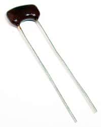
mica capacitorMica, a phyllosilicate, is a group of hydrous potassium/aluminum silicate material. It is a rock-forming mineral exhibiting a two-dimensional sheet or layer structure. That means it is possible to split mica into thin sheets. The biggest advantage of mica is the excellent stability of its electrical, chemical and mechanical properties. This property makes mica a suitable material for use as a dielectric when making highly stable and reliable capacitors. Silver-mica capacitors are useful at high frequencies, because of their low resistive and inductive losses and high stability over time.

Delved in India, Central Africa and South America, the most commonly used are the muscovite and phlogopite mica. While the first has superior electrical properties, the latter has a higher temperature resistance. Mica capacitors are expensive as the raw material composition has high variation, requiring inspection and sorting. Silver mica capacitors have sandwiched mica sheets coated or plated with silver on both sides. The assembly is then encased in epoxy to protect it from the environment.

Tolerance and Precision

Among all types of capacitors, silver mica capacitors offer the lowest tolerances, as low as +/-1%. In comparison, ceramic capacitors have tolerances going up to +/-20% and electrolytic capacitors can have more.

The design of a silver mica capacitor does not allow any air gaps inside. Additionally, the entire assembly is sealed hermetically from the environment. That allows the mica capacitor to retain its value over long periods. As the assembly is protected from the outside effects of air and humidity, the capacitance of a mica capacitor remains stable over a wide range of temperature, voltage and frequencies. The average temperature coefficient of mica capacitors is around 50 ppm/°C.

Losses

Mica capacitors have a high Q-factor. This comes from the low resistive and inductive losses exhibited by these capacitors. That makes them a suitable choice for use at high frequencies, but it comes at a price – silver mica capacitors are expensive.

It is difficult for manufacturers to make silver mica capacitors of larger capacitance value. Typically, this ranges from a few pF up to a few nF. However, they can stand high voltages and mica capacitors are usually rated for voltages between 100 and 1000 volts. Special mica capacitors are rated up to 10KV and these are mostly for use with RF transmitters.

Applications

You can use silver mica capacitors wherever the application requires low capacitances, high stability and low losses – especially in power RF circuits – requiring very high stability.

You can also use silver mica capacitors in high frequency tuned circuits such as oscillators and filters. Pulsed applications such as snubbers also use mica capacitors as they can withstand high voltages. If cost is an important factor along with tolerance and low losses, you can replace mica capacitors with class I ceramic capacitors. Ceramic capacitors are available at a fraction of the price of mica capacitors.

Mica capacitors are available as surface mount versions as well. This offers several benefits over radial or axial assemblies. By eliminating the leads, SMT designs offer a smaller device size that can be mounted directly to the PCB – resulting in a more compact design and greater mechanical stability.

More Italfarad, Ducati & Gentex Motor Start & Run Capacitors in stock!

more motor start capacitors in stock!

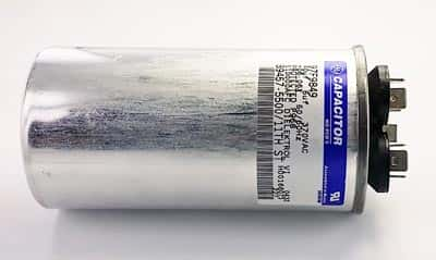
You’ve been asking for them – now we have them. We’ve added more values to our motor start and motor run category including some from Italfarad, Ducati and Gentex.

Check out our full selection at https://www.westfloridacomponents.com/MotorStart-RunCapacitors.html.

Need a different value? Ask us, we might be able to get them for you!

What is a capacitor used for?

Just as a bucket holds water, a capacitor holds charge. In fact, the world’s first capacitor was in the shape of a jar and was aptly named the Leyden jar. However, the latest capacitors do not look anywhere close to a jar. In its simplest form, a capacitor has two conductive plates separated by a dielectric. This helps maintain an electric charge between its plates. Depending on the type, different materials are used for the dielectric, such as plastic, paper, air, tantalum, polyester, ceramic, etc. The main purpose of the dielectric is to prevent the plates from touching each other.

The Leyden jar was invented in the 18th century, at the Netherlands University. It was a glass jar coated with metal on both the inside as well as the outside, with the glass effectively acting as the dielectric. The jar was topped off with a lid. A hole on the lid had a metal rod passing through it, with its other end connected to the inner coat of metal. The exposed end of the rod culminated in a metal ball. The metal ball and rod was used to charge the inner electrode of the jar electrically. Experiments in electricity used the Leyden jar for hundreds of years.

A capacitor can be used in a number of different ways, such as for storing digital data and analog signals. The telecommunication equipment industry uses variable capacitors to adjust the frequency and tuning of their communications equipment. You can measure a capacitor in terms of the voltage difference between its plates, as the two plates hold identical but opposite charge. However, unlike the battery, a capacitor does not generate electrons, and therefore, there is no current flow if the two plates are electrically connected. The electrically connected plates rearrange the charge between them, effectively neutralizing each other.

A naturally occurring phenomenon, lightning, works very similar to a capacitor. The cloud is one of the plates and the earth forms the other. Charge slowly builds-up between the cloud and the earth. When this creates more voltage than the air (the dielectric) can bear, the insulation breakdown causes a flow of charges between the two plates in the form of a bolt of lightning.

As there is only a dielectric between the two plates, a capacitor will block direct current but will allow alternating current to flow within its design parameters. If you hook up a capacitor across the terminals of a battery, there will not be any current flow after the capacitor has charged. However, alternating current or AC signal will flow through, impeded only by the reactance of the capacitor, which depends on the frequency of the signal. As the alternating current fluctuates, it causes the capacitor to charge and discharge, making it appear as if a current is flowing.

Capacitors can dump their charge at high speed, unlike batteries. That makes capacitors eminently suitable for generating a flash for photography. This technique is also used in big lasers to get very bright and instantaneous flashes. Eliminating ripples is another feather in the capacitor’s cap. The capacitor is a good candidate for evening out the voltage by filling in the troughs and absorbing the crests.

Variation of Capacitance of Ceramic Capacitors with Voltage and Temperature

The ceramic capacitors that you work with in the lab have two or more alternating layers of a metal acting as the electrodes and a ceramic acting as the dielectric. The capacitance measured in farad represents the charge stored in a capacitor at a particular applied voltage. The quantity should be a constant for a particular capacitor at all values of applied voltages and temperatures.

Capacitor Categories

While working with Class I capacitors, you may find that their capacitances do not deviate from the expected values. However, Class II and Class III capacitors do show a marked deviation from the rated values. These capacitors have greater volumetric efficiencies, however. This means that they offer higher capacitances compared to the volume occupied by the capacitors.

Identifying Codes

An alphanumeric code of three characters designates the type of a class II capacitor. The first and second characters of the code indicate the lower and upper limits of temperature and the third character specifies the change of capacitance within the range.

Take the case of X7R, which is a popular Class II capacitor. The letter X indicates a lower limit of temperature of -55°C and the number 7 indicates an upper limit of +125°C. The third character R points to a change in the actual capacitance by +/- 15% from the rated value while the device is working within the temperature range defined above.

Deviation of Capacitances

In other words, you can expect that an X7R capacitor of a rated value of 4.7 microfarad might show a capacitance of 3.9 microfarad, while working under these temperature limits. However, it is a common occurrence to find that capacitors in certain circuits show a much more remarkable drop from their rated values. An X7R capacitor can exhibit a drop of 20%. Certain other Class II capacitors may show a drop as significant as 80% of their rated values of capacitances.

The real fact is that the rated capacitance value of a capacitor holds for a particular value of the applied voltage, also called the DC bias voltage. If the bias voltage is different from the specified value, the capacitor will offer a capacitance that is different from the rated value.

For instance, if you choose a capacitor of 4.7 microfarad designed to operate at 16 V, it may offer a capacitance as low as 1.5 microfarad while working at 12 V.

The code used to identify the capacitors does not indicate the exact variation of capacitance with the applied DC bias voltage. However, it is a known fact that Class II capacitors designated by the letter X are the most stable. The capacitors designated by the letter Y are less stable under adverse environmental conditions while the Z capacitors are the least stable.

Material Used

To understand the problem, you need to study the data sheet for capacitors, which indicates the variation of capacitance with the applied bias voltage. The data sheet illustrates another interesting fact regarding capacitor sizes. A larger capacitor offers a greater capacitance at a particular DC bias voltage than a smaller one identified by the same alphanumeric code. Hence, you can expect a better performance with a larger capacitor than with a smaller capacitor of the same code. A possible reason for the fact could be that manufacturers have to compromise on the material while making smaller capacitors of the same code.

How Professional Grade Capacitors Are Used In the Automotive Industry

The challenging conditions faced by automobiles have compelled component manufacturers in the automotive industry to come up with superior capacitors. Two of these advanced capacitors are professional grade capacitors of tantalum and niobium oxide.

A capacitor is comprised of two conducting plates separated by a dielectric (insulating) medium. One plate maintains a positive charge while the other maintains a negative charge.

Benefits of Professional Grade Tantalum Capacitors

A tantalum capacitor has a pellet of tantalum as the positive end separated from the negative conductor by a dielectric, which in this case is a thin layer of tantalum oxide formed on the tantalum pellet surface.

Professional grade variety of tantalum capacitors has several advantages over standard tantalum capacitors. Manufacturers adopt strict design specifications to construct the capacitors and use thicker and better dielectrics. In addition, the manufactures check the devices for high surge current and burn-in procedures.

The use of these capacitors results in a low failure rate of 0.5% in 1000 hours. In addition, the leakage current is almost 75% less than that in conventional tantalum capacitors. Manufacturers make professional grade capacitors available with low and standard equivalent series resistances (ESR). This makes these components suitable for several types of control circuits in automobiles.

The low ESR capacitors are particularly useful in airbag modules, engine control modules and power supply modules.

Functioning at High Temperatures

Automotive engineering requires placing electronic components close to sources of heat like engines, gearboxes, AC circuits and headlights. The temperatures in these regions may be in the region of 175°C. Since tantalum capacitors can function over a wide temperature range from -55°C to +175°C, they are suitable for use in these regions.

Niobium Capacitors

How The Automotive Industry Uses Capacitors

Before deciding on a tantalum or niobium oxide capacitor in a particular automotive circuit, the industry thinks about the nature of the circuit and the device using it. The first factor, which is the maximum voltage drop across the load in the circuit, determines the voltage rating of the capacitor. The second factor is the applied DC voltage. The applied voltage must be 50% of the rated voltage for the capacitors. This takes care of an unexpected surge in voltage. The third factor is the maximum value of the operating temperature. The capacitor selected must be able to withstand the temperature of the operating device.

A circuit operating under high temperature conditions (up to 125°C) can expect to see additional voltage surges. It is crucial that capacitors employed can endure these issues.

Can capacitors act as a replacement for batteries?

It is common knowledge that capacitors store electrical energy. One could infer that this energy could be extracted and used in much the same way as a battery. Why can capacitors then not replace batteries?

Conventional capacitors discharge rapidly, whereas batteries discharge slowly as required for most electrical loads. A new type of capacitors with capacitances of the order of 1 Farad or higher, called Supercapacitors:

• Are capable of storing electrical energy, much like batteries
• Can be discharged gradually, similar to batteries
• Recharged rapidly – in seconds rather than hours (batteries need hours to recharge)
• Can be recharged again and again, without degradation (batteries have a limited life and hold increasingly lower charge with age, until they can be recharged no longer)

The Supercapacitor would thus appear to be one up on the batteries in terms of performance and longevity, and some more research could actually lead to a viable alternative to conventional fuel for automobiles. It is this concept that created the hybrid, fuel-efficient cars.

However, let us not jump to conclusions without considering all the aspects. For one, the research required to refine this technology would be both time and cost intensive. The outcome must justify the efforts in terms of both time and cost. The negatives must be carefully weighed against the advantages enumerated above, some of which are:

• Supercapacitors’ energy density (Watt-hours per kg) is much lower compared to batteries, leading to gigantically sized capacitors
• For quick charging, one would need to apply very high voltages and/or currents. As an illustration, charging a 100KWH battery in 10 seconds would need a 500V supply with a current of 72,000 Amps. This would be a challenge for safety, besides needing huge cables with solid insulation, along with a stout structure for support
• The sheer size of the charging infrastructure would call for robotic systems, a cumbersome and expensive set up. The cost and complexity of its operation and maintenance at multiple locations could defeat its purpose
• Primary power to enable the stations to function may not be available at remote locations.
Many prefer to opt for the traditional “battery bank” instead. The major problem of lead acid battery banks is the phenomenal hike in the cost of lead and the use of corrosive acid. Warm climates accelerate the chemical degradation leading to a shorter battery life.

A better solution, as often advocated, is to use a century-old technology in which nickel-iron (NiFe) batteries were used. These batteries need minimal maintenance, where the electrolyte, a non-corrosive and safe lithium compound, has to be changed once every 12-15 years. To charge fully, it is preferable to charge NiFe batteries using a capacitor bank in parallel with the bank rather than charging with a lead-acid-battery charger.

Though NiFe batteries are typically up to one and a half times more expensive, lower maintenance cost more than offsets the same over its lifetime.

To summarize, the Supercapacitor technology would still have to evolve in a big way before actually replacing batteries although the former offers a promising alternative to batteries.

image courtesy of eet.com

Box Capacitors – so many in one place!

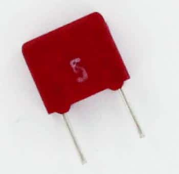
We’ve been very busy expanding another category for you: Box Capacitors.  Now in stock and ready to ship are more than 60 different values of box capacitors. In general, box caps are constructed of polyester film or metallized polypropylene. Some of the more popular manufacturers are Wima, Mallory and Philips.

In addition, (and somewhat related), we’ve greatly expanded our suppression and safety capacitor category. Between both categories, there are almost 75 new products added this week alone! Look for quantity discount pricing on almost all of the capacitors.

And, as always, we do not require a minimum purchase and our first class mail shipping rates are still a very reasonable $3.50 for all US purchases up to $15.00.

Motor Start Capacitors vs Motor Run Capacitors

motor run capacitorWe are often asked about the difference between the two different types of motor capacitors: motor run and motor start. Here are the basic differences between the two:

Motor Start Capacitors
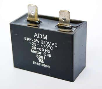
The primary purpose of a motor start capacitor is to briefly increase the motor starting torque as well as to allow a motor to be cycled on and off very quickly. It operates in the circuit by staying active long enough to allow the motor to be brought to 3/4 of it’s full capacity. It is removed at that point by a switch in the circuit. You will find that the voltage rating is often one of these four: 125VAC, 165VAC, 250VAC, and 330VAC.

Motor Run Capacitors
Motor run capacitors will then operate after the circuit is started. Using a motor run capacitor will run the motor with greater efficiency. Motor run capacitors are designed for continuous duty. They are energized while the motor is in operation. You will often find motor run capacitors with a voltage rating of 370VAC or 440VAC with a capacitance of 1.5uF – 100uF. Typically, the construction material is polypropylene film.

Operational information
Electric motors that are single phase require a capacitor for a second-phase winding. If you use the wrong motor run capacitor, the rotor may hesitate due to an uneven magnetic field. The hesitation may result in performance issues such as a noisy or overheated motor, increased energy consumption and general decreased performance.

Faulty motor capacitors
You can sometimes spot a faulty motor run capacitor by it’s swollen appearance – or it may have blown and become leaky. Of course, these capacitors should be carefully replaced. In addition to an outright capacitor failure, the capacitance may become reduced over time. Capacitors that are operating with a decreased capacitance may create performance issues. Again, these capacitors should be carefully replaced.

Opening Up and Tearing Down an IPOD Shuffle

Opening up and tearing down an IPOD Shuffle to see what’s inside…

The 3rd Generation of the IPOD Shuffle is a wonder of technology….1000 songs stored in an aluminum case smaller than a disposable lighter.

Did you ever wonder what electronic components make up the guts of an IPOD Shuffle?

You might be surprised at what goes into the circuitry of the IPOD Shuffle. In descending order by percentage of cost, the main components are:

logic, memory, metals, rechargeable materials, connectors, PCB, crystal, misc, capacitors, transistors, analog, diodes, magnetic, and plastics.

Here’s a partial breakdown by number of electronic components:

Capacitors – 65+
Resistors – 50+
Diodes – 4+

Pretty amazing what goes into equipment that measures only 45.2mm x 17.5mm x 7.8mm when fully assembled! This is possible because the components are extremely small surface mount components.

If you look at the cost breakdown by component family, it’s just as revealing. Naturally, the largest share is for memory in the form of IC’s. Over 70% (about $12.00 worth) is for logic and memory.

How to Read Capacitors

Capacitance Values – and How to Read Them

Capacitors are used in a wide range of electronic components and circuits. They form an integral part of electronics. The capacitance of capacitors is measured in a unit known as Farads, represented by the letter ‘F’. A capacitor that has higher capacitance can be used for storing more charge as compared to one with a smaller capacitance value.

One Farad is a very high value for capacitance and usually smaller units are used, namely pico farad, nano farad etc. And as the capacitors are physically very small in size, their capacitance needs to be identified with a code mentioned on the capacitor itself. The exception to this is electrolytic capacitors that are big enough to have the capacitance value written directly on them.

Ceramic and film capacitors usually have a coded value marked on them. If the value marked on them is a two-digit whole number, then the capacitance is equal to the value mentioned in pico Farads. Thus a code of “10” implies that the capacitance is equal to 10 pico farads.

A three-digit whole number includes the first two significant digits, and the third digit as the multiplier (indicating the number of zeroes), and gives the value in pico Farads. Thus a code of “104” means, 10 multiplied by 10,000, giving the capacitance as 100,000 pF or 0.1 uF.

If a decimal number is used as the code on the capacitor, then the capacitance is equal to value mentioned in micro Farads. For instance, “.1” mentioned on the capacitor would imply 0.1 uF.

Finally, a whole number followed by the alphabet ‘n’ means the capacitance is equal to value mentioned in nano Farads.

In addition to the capacitance, the code on these electronic components can also be used for indicating the tolerance, voltage, and temperature properties.

470pF 3000V Capacitor

470pF 3000V Capacitor

In the example above, the capacitor reads:

471M

3KV

The 471 is deciphered as 470pF; M=20% tolerance; 3KV=3,000V

Here are the codes for tolerance:

B +/- 0.1pF
C +/- 0.25pF
D +/- 0.5pF
E +/- 0.5%
F +/- 1%
G +/- 2%
H +/- 3%
J +/- 5%
K +/- 10%
M +/- 20%
N +/- 0.05%
P +100% ,-0%
Z +80%, -20%