Solar Energy is Hot!

Solar radiation, as well as other solar resources like wind power, wave power and hydroelectricity make up over 99% of the renewable energy sources available to us. Amazing!

I remember reading about google’s goal of installing enough solar panels to generate electricity for 50,000 homes. They have made a real commitment to investing in renewable energy resources.

Imagine if we each made JUST ONE home appliance solar powered? We can start small – like a solar powered I-Pod charger or some solar powered outdoor lights. How about a solar powered cell phone charger? Once you realize how easy it is to begin using solar power, you’ll be ready to convert some of your bigger energy drains…..like maybe a hot water heater?

People are motivated to convert to solar power for a variety of reasons. Some look at the financial benefits while others are more concerned about the earth.

We all have been hit hard this year with rising fuel costs. My cars cost more to fill up, my home cost even more to cool down, and I just got a huge bill from my propane company. The only fuel source that cost the same this year as last is my solar bill. It’s still ZERO!

Although I personally got involved with solar energy for financial reasons, my focus has changed over time. I am glad to be doing just a little bit to reduce our dependence on non-renewable energy sources.

If you’re ready to take the plunge, take a look at our solar panels and solar controllers. Remember to take your time, do your homework, then be prepared to reap the benefits of solar power for years to come.

What is a heatsink?

When current flows through a resistor, part of the electrical energy is converted into heat that gets dissipated into the surroundings. If the heat generated is not quickly removed, it can permanently damage the electronic circuit. Heatsinks are devices that are capable of removing the heat from electronic devices and speedily dissipate it into surroundings.

Heatsinks can be passive or active devices. Passive heat sinks consist of fins made generally

Voltage Regulator in a Heatsink

Voltage Regulator in a Heatsink

of aluminum that provide a large surface area for heat dissipation. Active devices in addition have fans that circulate the air around the sink for faster removal of heat. The heat dissipation in a heatsink takes place principally through convection either natural or forced.

Heat transferred through convection is proportional to the temperature difference between the heatsink and the surroundings. The constant of proportionality is called convection coefficient. Mathematically, q = h x A x ∆t, where q is the heat dissipated by convection, h is the convection heat transfer coefficient, A is surface area and ∆t is the temperature difference between the heat sink and the surroundings. The coefficient h is a function of velocity of air circulating around the heatsink among other things. Thus higher the speed of air circulating around the heatsink faster is the heat dissipation.

Heatsinks are widely used for cooling electronic devices and the surrounding circuit like the CPU in a computer. With the need to make electronic devices more compact and powerful, the need to make high capacity heatsinks is increasing. Modern heatsinks are manufactured by extrusion, die casting, cold forging etc. Heat pipes have been used in heatsinks as they are lighter and more efficient compared to solid pipes of same size. Anodized aluminum is the most common material used in making heatsinks, although copper, silver and even gold have been used.

Custom Tube Amp in Time for Halloween

Steve W. from Peterborough, Ontario, Canada sent me some new pictures of his latest projects.

He built this particular amp for himself. It’s a 40 Watt per channel 807 that used 8 of our 470uF 400V Electrolytic Capacitors .

The finish is blue perl clear coat – that finish is perfection!

We’ll be posting more of Steve’s custom tube amps over the next couple of days.

As always – great job, Steve!

Halloween Amp

Halloween Amp

Halloween Amp2

Halloween Amp

Halloween Amp3

Halloween Amp

Op Amps – Then and Now

Op Amps – Then and Now

Op amp is the commonly used name for operational amplifiers, which are widely used electronic components. Op amps are often seen on many surface equipment designs and logging tools.

The name ‘operational amplifier’ comes from the use of such high gain amps in performing mathematical operations for analog computer operations and is said to have been coined in 1947. A 
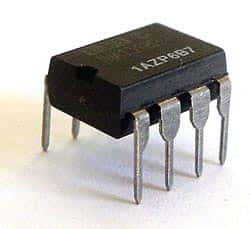
lot of study was done in the field and the initial operational amplifiers, based on vacuum tubes, were a result of the research done in Bell labs. By 1960’s, vacuum tube op amps had given way to solid state devices and hybrid operational amplifiers were entering the scene.

The first IC operational amplifier was developed in 1963 by Bob Widlar and was called Fairchild µA702. It was not a success because of a number of bugs. But Widlar’s next design, which was the µA709, was hailed as milestone in design. A number of designs followed including the very popular µA741. A number of precision op amps like OP7, OP27 and OP37 are commonly used in logging electronics.

In the initial days, these electronic components were based on NPN bipolar process and because of the slow PNP transistors of the time; the speed of the amps was limited. The LM118/218/318 model tried to solve the problem but did not meet with much success. The only fast IC op amps were the ones owned by Harris, the HA2500 as well as the HA2600, and were quite popular despite their high cost.

FET input operational amplifiers though highly advantageous in downhole tool applications, did not enter the scene due to engineering problems. However with the introduction of the ion implantation process in 1974, their manufacture became possible and the LF155/156/157 series was introduced by National Semiconductor, and OP15, OP16, and OP17 by PMI. The TL06x, TL07x, and TL08x models introduced by Texas Instruments (TI) in 1978 went on to become industry standards.

The CA3130 employing a P-channel MOS input with a CMOS output, set the stage for CA3140 having a MOSFET input and a bipolar output which caught the eye of many logging tool companies. This model has many advantages including good bandwidth and military temperature range, and continues to be used and manufactured even now.

Tact Switch – SKPFABA010

We’ve been selling a lot of this one particular switch – it’s called a long travel tact switch; manufactured by ALPS.

Here are some of the features of this switch:
— Dimensions: 8mm x 8mm
— Suitable for automotive applications due to its high operational force
— Malfunctions are prevented due to it having a longer travel than most conventional tact switches
— Easily mounted on a PC board with snap in leads
— Some of the output terminals can be used as jumper leads which makes the circuit arrangement simple

Here are some other uses:
— automotive electronic equipment
— communication devices
— measuring instruments

These switches are available right now – they have been priced lower than any other distributors.

Be sure to check them out next time you need a 12V tact switch!

Desoldering – Why is it Necessary and How is it Done?

Soldered joints, if improperly done, may need to be ‘desoldered’ or the solder removed in order to resolder them. A poorly soldered joint can result in failure of the electrical circuit over a period of time. This can happen for a number of reasons. Low quality solder or failure to properly clean the surface before soldering or even lack of proper technique and corrosion of the joint due to leftover flux, movement (shake) of the joint before the solder has cooled may all cause a poor soldered joint.

There are other reasons you might need to desolder a joint. Desoldering and resoldering may also be required in order to replace a defective electronic component or if you are troubleshooting an electrical circuit.

One common method of desoldering is to use a desoldering pump which is a vacuum pump similar in operation to a bicycle pump in reverse. The spring loaded plunger breaks the solder and gets sucked away by the pump. Repeated operation of the pump may be required in order to completely desolder a joint, or you can also use the solder pump to take up the bulk of the flowing solder and finish up the job with solder wick. Either way works – the solder wick is more expenisve so you may want to use both if you have a large job. Be careful – the pump should be operated carefully so that no damage the PCB or the electronic components occurs.


A solder wick or braid is an alternative to desoldering pumps. Here the copper wick is placed over the joint and the solder is melted by means of soldering iron. The solder gradually flows into the wick and hence gets removed. The wick must be removed from the PCB before it cools down as otherwise it may damage the board.

Resistors In Series

Electronic components used in electronic circuits to regulate and limit the flow of electric current in the circuit are known as Resistors. Resistors can be connected in two basic configurations – in series and in parallel.

When connected in a series connection, the resistors are connected in a line. The current flows through the resistors one after the other.

When the resistors are connected in such a configuration, they exhibit the following properties:

The current flowing through each of the resistors is the same, that is, I total = I1 + I2 + I3…and so on. This is due to the fact that there is only one path for the current to flow through. The second property that they exhibit is that the total voltage drop across all the resistors connected in series is equal to the sum of the individual voltages of the resistors, that is, V total = V1 + V2 + V3…

Now since, V = IR, so, V total = I R equiv, which comes down to,
I R equiv = I1.R1 + I2.R2 + …, and since I1 = I2 = I3 .., we have
I. R equiv = I. (R1 + R2 + R3..), or R equiv = R1 + R2 + R3..

So the equivalent resistance of these electronic components connected in series is the sum of the individual resistances.

Resistors in series are often used for obtaining specific higher resistance values which are otherwise not available. They are also used in voltage divider circuits. A common application is in household wiring.

Early Crystal Radios

Requiring no battery, the crystal radio was one of the earliest forms of radio having been developed in the late 1800s and early 1900s. At this time the crystal radio sets were used to receive Morse code messages, but as time progressed the voice messages could also be received by such sets. This progression had much to do with an improvement in materials, which included the diodes and tuning coil. Even with an improvement in materials though, the construction of a radio set was fairly simple to achieve.

By the 1920s and 1930s radio was taking off, but the sets were expensive objects to buy and so the crystal radio was the cheap alternative that could be built at home. Most major newspapers would run guides on how to build such radios, and it was information that was put to good use during the Second World War. During the war, allied Prisoners of War made use of the materials that they had on hand, to build their own radios, to find out news of the fighting. The soldiers would use recovered wire for the tuning coil and antenna, and make diodes from everyday material, like the pencil lead.

The crystal radio is still used by many people around the world today, although now it is usually a hobby rather than a necessity. In most cases, radio sets are now fairly cheap and mass produced making the building of a crystal radio a pleasure rather than something that needs to be done.

The Basics of Potentiometers

Potentiometer Basics

A potentiometer is a manually variable resistor. It has 3 terminals, one of which is connected to ground, the second to a current source and the third to a sliding contact that runs along a strip of resistor. The varying resistance is used to control other parameter like volume. Potentiometers are widely used electronic components used in volume control, brightness control etc. though recently they are being replaced by digital control circuits.

A potentiometer can regulate the amount of current flow in a circuit. In this case, the maximum current flow is limited by the resistivity of the variable resistor. The variable resistor can be in the form of a linear strip or a circular strip. In a linear potentiometer, the cross section of the resistor is constant and the resistance varies directly with the length of the resistor. In a logarithmic potentiometer, the resistor tapers from one end to the other and the cross section varies likewise. The variation of current flow is logarithmic in this case and is used in audio amplifiers.

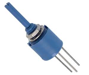
A digital potentiometer is digital equivalent of variable resistor potentiometer. It is a digitally controlled electronic component with built in IC or a digital to analog converter. It is widely used in instrumentation amplifiers. It has limitation of being restricted to currents of a few milli amperes and voltage in the 0 to 5V range.