Category Archives: Wire

How is a Wire Harness Made?

Many sectors, including industrial and consumer electronics, continue to use wire harnesses, and their use is increasing continuously. Therefore, there is an urgent need to understand the process of manufacturing this vital component. Wire harnesses link different electrical or electronic modules to allow the complete system to work seamlessly.

Wire harness assemblies are a bunch of wires processed with a protective sheath. They may end in different types of terminations. Harnessing is important as it organizes the wires for easy implementation. Wire harnesses must not be confused with cable assemblies, which bind multiple covered wires with a protective covering, enabling them to work in harsh environments.

The use of wire harness assemblies results in several advantages. The organized wires optimize space while helping to improve assembly times. The harness helps in customizing the appliance to its bespoke needs. The protective covering on the wires improves equipment safety while improving the life of the wires. A variety of appliances use wire harnesses extensively. These include heavy equipment, panel displays, flight simulators, control panels, vehicles, and more.

The wire harness manufacturing process begins with design. Each product requires a custom-designed harness. It is imperative to choose each component of the wire harness carefully to achieve full functionality and life.

The primary requirement is the length of each wire in the harness. As the wire may require routing through the equipment, the length of individual wires in the bunch may differ. The length of the wires may also depend on their diameter, as thicker wires require more space to bend.

Each wire must also be considered for the maximum current it will carry. In a wire harness, some wires may carry power while some may carry low-frequency signals. They will require wires of different gauges.

Once the designer determines the length and gauge of each wire, they must concentrate on the wire terminations, which are necessary to connect each wire to its starting and ending points. This depends on the end termination of the two devices the wire will be joining. The terminations may use lugs, crimps, connectors, or something similar.

Once the wires are bunched together to form the harness, it will be difficult to identify them individually. Therefore, the designer will require some means of identifying individual wires in the bunch. Ferrules are a low-cost choice for this purpose. They are available in different diameters and individually marked with numbers and alphabets. By using the same combination of ferrules with numbers and alphabets on both ends of a wire, it becomes easy to identify the wire, even after bunching it with several others. However, this identification is only necessary if the operator will connect each wire individually. They are not necessary if the termination ends in a connector.

Next, wire harnesses may require a jig to form them into the final shape necessary for implementation in the system. Once the operator arranges or dresses the wire harness in the jig, they may require a means to bunch all the wires together. This may take different forms, like a plastic wire or sheath covering the full length of the wire harness.

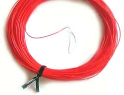
Different Types of Industrial Cables

To wire up different components within electronic gadgets, hook-up and lead wires may be adequate, but the electric industry needs a vast variety of industrial cables to remain connected. Chief among these are power cables to carry high voltages and currents, and cables necessary for industrial automation and process control. Cables may conform to multiple standards such as UL, CSA, and others. Cables often have to transmit power or signal in industrial environments that may harbor the harshest conditions involving physical abuse, high temperature, ozone, chemicals, oil, and other demanding situations.

Challenges and Solutions

With increasing demand from the industry, manufacturers are producing cables for automation and seamless data communication. To support proliferation of mission-critical signal transmission, cable manufacturers offer high quality, high-availability line of industrial cabling and connectivity products.

Seamless Connectivity from the Enterprise to the Sensor

For the most robust and reliable factory networking, manufacturers also offer network switches, I/O modules, and other devices. Users choose their cables from a vast selection of configuration, insulation and jacket materials, shielding options, high-flex capabilities, and other options.

Manufacturers must maintain product consistency for ease of termination and assembly. For instance, precise control of diameters of jacket and insulation along with thickness of concentric wall ensure fast and reliable supplication in automated high-speed equipment.

Shielding

Depending on their use, industrial cables also require highly effective protection from EMI and RFI. There is increasing demand for innovative designs with shielding technology using foil and braid configurations. Manufacturers offer 100% shield coverage improving the protection over a wide range of frequencies. Apart from this, cables also require electrostatic shielding, and sometimes, extra insulation and mechanical strength. Overall, the cable shielding needs to be lightweight, strong, flexible, thin, but extremely effective.

Armoring

For cables requiring maximum physical protection in the harshest of environments, armoring technology is the solution. Armoring offers added advantages such as reduced cost of conduit, easier installation and re-routing, while it provides additional shielding.

Typical armoring of power, instrumentation, and data cables involves interlocking aluminum or steel armor, or continuous corrugated armor of aluminum. Some manufacturers also offer cables with corrugated or smooth protective metal tapes.

Insulation and Jackets

Cable manufacturers offer a large variety of insulation and jacket compounds, often their own formulation. These provide superior performance under different hostile environmental conditions. Cables are typically graded as Class I, II, or III, according to whether they are suitable for hazards differentiated by Division 1 or 2.

For instance, cables suitable for Class I, Division 1 Hazards are used in locations where flammable vapors or gases may exist under normal operating conditions. Cables suitable for Class III, Division 2 Hazards may be used in locations that contain easily ignitable flyings and fibers under abnormal conditions.

Intrinsically Safe

Not all environments need be hostile. Occasionally, under normal or abnormal conditions, equipment and wiring may be incapable of releasing adequate amounts of electrical energy to ignite a susceptible, specific hazardous atmospheric mixture. Manufacturers offer cables with light blue color with approved sealing and separation for use in such situations.

Cable manufacturers offer the most comprehensive line of industrial cabling solutions today. This helps not only for networking on the factory floor or process equipment and devices to their controllers, but also to the control room, and for relaying data between the engineering department, control room, and various office sites or remote manufacturing locations.

The humble cable assembly

In a project, the major focus is on active components, circuit design and software, in that order. However, what we tend to overlook is the humble cable and connectors that link all the components together. Nonetheless, along with the more glamorous components, the humble cable assemblies also define the success and reliability of your project.

Active devices and test equipment, being very tangible, always seem to command greater respect compared to the attention bestowed on the almost invisible cable and connector assemblies. This is true in both the prototyping and production cycles. However, this may prove unwise in the long run. Although wireless connectivity is catching up fast, in reality, hard-wired signal interconnects are still irreplaceable and indispensable parts of nearly all systems.

Once design engineers work on the gigahertz and higher ranges in their projects, it gets more challenging for them as cable assemblies play a more active role, both practically and figuratively. The importance of cables and connectors can be seen in RF/microwave-centric web sites and publications that devote more than one-third of their ads and content to the subject. In the high-frequency world, phase matching between two nominally identical assemblies is very often critical. This arena talks about second- and third-order parameters and the temperature coefficient of the cable’s specification gains importance. High-frequency designers treat cable assemblies with respect. For them, the assemblies are energy waveguides that are carefully engineered and modeled with precise dimensions, tested and fabricated.

Just as there are many cases of counterfeit components, mostly ICs and sometimes passive, Cabling and Installer have reported fake cable assemblies as well. In fact, this was one of their top 10 articles in 2014. Fake cable assemblies do not fully meet the operating specifications. They may somehow work, but fall short at higher data rates, or they cannot provide the specified power when used for PoE.

Not only the electrical performance, fake cable assemblies compromise safety as well. In most installations, a cable’s insulation is very important factor, as it must be fire-rated so as not to support combustion. This is usually not noticed unless a fire breaks out. Some fake assemblies even substitute the necessary copper wire with a brittle aluminum core and copper cladding.

It is very easy to make fake cables, stamping them with almost any rating required. Very few people test and verify the cable performance when faced with falling data rates and rising BERs. In most cases, we remain content with the Cat5/UL rating stamped on the cable, taking them as given. This is a concern that is bothering not the high-frequency instrument manufacturers alone, but also the audio industry, the aircraft industry and electrical distribution companies. Who can say the OFHC or Oxygen Free, High Conductivity audio cable is not actually a plain copper cable slapped with an OFHC label?

With the world now reaching out to 100GHz and beyond, cables are getting thinner, tinier, with hair-thin wires, and corresponding match-head sized connectors. At such high frequencies, every bend radius, routing guide stress, torque and abrasion from sharp edges becomes important and critical.

How do fiber optic cables carry light?

Nowadays, nearly everyone is talking about fiber-optic cables. These cables are now commonly used in telephone systems, cable TV systems and the Internet. One of the main advantages with optics cables is their huge bandwidth. That means fiber optics cables can carry far more signals than copper wires can. Usually made of optically pure glass, these cables are very thin – nearly as thin as human hair. Because of their high signal carrying capacity, optical fiber cables are also used for mechanical engineering inspection and in medical imaging. Optical fiber cables are made of long, thin strands of extremely pure glass. With a diameter close to that of human hair, several strands are bundled together, to form cables that are used to transmit light signals over long distances. When examined closely, each single fiber can be seen to consist of three parts.

The central core of the fiber is made of glass and this is where the light travels. The core is covered with a cladding, which effectively reflects light back into the core. The core is surrounded by a buffer coating, mainly for protecting the fiber from moisture ingress and physical damage. Optical cables contain hundreds or even thousands of such optical fibers arranged in bundles. On the outside, a jacket, also called the cable’s outer covering, protects the cable.
In general, there are two major types of optical fibers – single-mode and multi-mode. With a small core of about 9 microns in diameter, single-mode fibers can transmit infrared laser light having wavelengths of 1,300 to 1550 nanometers. On the other hand, multi-mode fibers have core diameters of about 62.5 microns, capable of transmitting infrared light of wavelengths from 850 to 1300 nanometers.

Other types of optical fibers can be made of plastic as well. These usually have a larger core of about 1 mm diameter, capable of transmitting visible red light of wavelength 650 nm, such as from LEDs.

Light always travels in straight lines. This is easily seen when a flashlight beam is shown down a straight long hallway. You can see the entire length of the hallway until the next bend, but beyond which nothing is visible. However, placing a mirror at the corner will allow you to see round the bend. This is possible because light from around the bend strikes the mirror and reflects down the hallway. If the hallway were to be very winding with multiple bends, lining the walls with mirrors will help. Light bounces from side-to-side and travels down the hallway making the entire path visible. This is exactly how an optical fiber works.

Light travels through the core of the fiber-optic cable, constantly bouncing off the cladding. This follows a well-known principle of optics known as total internal reflection. Very little light is lost in total internal reflection from the cladding, allowing light to travel long distances within the cable.

Although the core is made from optically pure glass, some impurities remain. These degrade the light signal as it travels down the core. The extent of signal degradation depends both on the impurities present in the glass used for the core and the wavelength of the light traveling through it.

All about electrical wires

Recent advancements in wireless technology may have led many people to believe that soon, we would be able to do away with these squiggly, snaking, long implements we call wires. However hard we may try to hide them by burying them within walls and under the ground, the time is not yet ripe for a life entirely without wires. While we have to put up with wires all around us, it would be interesting to know something more about them.

Use of wires can be broadly categorized into two main classes of requirements – mechanical and electrical. While the mechanical requirements deal mainly with load carrying strength/capacity of the wire under use, the electrical requirements can be further subdivided into power and signal carrying capabilities. In this article, we will be talk about wires and their electrical requirements only. The materials with which wires are made, their dimensions and the nature of protection used depends to a large extent on whether the wire is required to carry power or signal.

Most wires within our houses and those carrying power are made of copper. Conductivity, malleability and cost are the main considerations that govern the choice. Copper is a good conductor of electricity, meaning it presents a low resistance to the flow of electricity through it. The metal is easy to bend and mold in the form of wires of different diameters. Since copper is abundantly available, the price is reasonable for residential use. Some wires are made of aluminum, which is cheaper than copper. However, its conductivity is lower than that of copper. For carrying the same amount of electricity, you need an aluminum wire with a larger diameter compared to that of a copper wire.

The nature of protection used on wires carrying electrical power depends on the voltage it is carrying and the environment in which the wire is used. For example, special cladding and fire-retardant protection is required for wires carrying high voltage electricity passing through an area with plenty of oil.

Compared to power handling wires, signal-carrying wires are of more varied types, depending on the application. For example, there can be connecting wires, RF coaxial feeders, screened cables, ribbon cables, data cables and many more. For most of these applications, the governing factor is the frequency of the signal rather than the voltage and current carrying capacity. Waveform distortion, crosstalk, noise and signal loss are more important rather than the amount of power transferred.

As long as the signal frequency is low, say below 1000 Hz or so, the material or construction of the wire does not matter greatly. However, as the frequency of the signal increases, the wire starts to behave like a non-linear entity and its inherent inductance and capacitance start to cloud its performance. With still higher frequencies, the signal is unable to retain its original waveform. To retain the high-frequency performance, people need to use special types of RF coaxial feeders, ribbon cables, screened cables, etc.

For example, to prevent loss of signal in screened cables, a low-loss insulator often surrounds the wire conductor. A braided sheath on the outside of the insulator acts as a shield and a PVC jacket protects the entire package.

Wire Bending Radius Guide

At West Florida Components, we get asked very often about wire bending radius. It is important to have guidelines when working with wire or cable in your projects, particularly projects that involve curves, ductwork and buildings. There are a few rules of thumb that come into play when you think about the bending radius of wire and cable. Following these rules will ensure that your wire and cable projects go off without a hitch!

Here is a chart to use: https://www.westfloridacomponents.com/wire-bending-radius.html