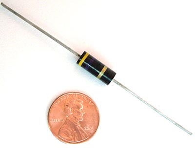
Allen Bradley resistors are one of the best sellers on the West Florida Components web site with good reason.
The following information has been compiled to aid in the everyday selection and application of Allen-Bradley hot molded resistors. The statements should be helpful in evaluating the use of all types of AB hot molded resistors in broad general terms, and are not to be interpreted to be precise or exact.
A comprehensive list is made of the standard normal resistance values in their available tolerance categories, the rated continuous working voltages for all hot molded types, the part numbers, and color codes – all information provided for all values from 1 ohm to 100M ohm, taking into account the available range of values for each type (as of 1985).

Allen Bradley Resistors
1 – Low value resistors exhibit less change due to humidity, temperature and voltage than high value resistors.
2 – Resistance changes due to increase in moisture content are always positive.
3 – Resistance changes due to humidity are temporary, and, in the case of Allen Bradley resistors, are reversible.
4 – Change of resistance which has occurred due to humidity may be essentially eliminated by conditioning the resistor at 100°C or by dry storage.
5 – The effects of humidity may be minimized by operating the resistor with as little as 1/10 rated wattage load.
6 – Resistance change due to load life is permanent and usually ultimately negative.
7 – Resistance change due to load life can be minimized 1% – 2% in many thousands of hours by 50% derating period. The same result can be attained by limiting the maximum operation surface temperature of the resistor underload to 100°C. Permanent resistance changes as a result of storage of temperatures below 100°C are negligible, even for extended time periods.
8 – Resistance change due to soldering is positive and may be permanent if the resistor has excessive moisture present in its body. It can be greatly minimized if resistors are dry at the time of soldering.
9 – The temperature characteristics of Allen Bradley resistors is positive above +80 and below -10.
10 – The temperature characteristics of Allen Bradley resistors is negligible from -10°C to +80°C.
11 – The voltage characteristic (negative) and the temperature characteristic (positive) of Allen Bradley resistors tend to cancel one another in an Allen Bradley resistor in an average operating conditions, where both significant voltage and elevated temperature are present.
12- The heat sink to which a resistor is connected affects its rating. Resistors operated in multiple should be derated unless adequate heatsinks are provided.
13 – The quality and reliability of Allen Bradley resistors is the same for, and independent of, any resistance tolerances shown on the resistor.
14 – Years of accumulated experience have shown that Allen Bradley hot molded resistors are unequaled for uniformity, predictable for performance, appearance, and freedom from catastrophic failure. Allen Bradley resistors are made by an exclusive hot molding process on automatic machines developed, built, and used only by Allen Bradley. There is such complete uniformity from one resistor to the next, million after million, and long term in-circuit performance can be predicted with usable accuracy. When used according to published ratings and recommendations, Allen Bradley hot molded fixed resistors will not open circuit nor exhibit erratic changes of resistance value. They are probably the most reliable of all electronic components.
This information was taken in part from the Allen-Bradley corporation reference book dated 1985.

