Category Archives: Newsworthy

Raspberry Pi Gesture Control

Many smartphones are capable of gesture control, where the phone can sense movement of the owner’s hands near it and respond accordingly. Now you can add the same features to the versatile credit card sized single board computer, the Raspberry Pi or RBPi. The features are provided by the Microchip 3D Gesture Controller, the MGC3130 GestIC and a 3D Touchpad.

The hardware you will need for implementing the gesture control is the MGC3130 Hillstar Development Kit, a 5V, 1.2A power supply with a microUSB connector and an RBPi Model B, preferably V2. Initially, you will need access to a PC for parameterization and for flashing the firmware on the MGC3130. After the flashing is over, the MGC3130 can communicate directly with the RBPi via the GesturePort available of the tiny MGC3130 board on the Hillstar dev kit. The Hillstar board needs signals EIO1, EIO2, EIO3, EIO6 and EIO7, which the RBPi supplies via its GPIO connector.

3D gesture sensing and control applications require capacitive sensing, which the MGC3130 handles aptly. You can either power the Hillstar board from the USB charger, or let the RBPi power it up directly. Once connected, the MGC3130 senses the North-South and East-West hand flicks. The EIOx pins flag the gestures sensed to the RBPi, which then acts on them according to actions already assigned.

The GestIC controller has Aurea, a free graphic shell working around it. Aurea allows parameterization of several planes of different sizes and configuration. These planes make up the capacitive sensing pad and you can calibrate and configure them with good precision. For programming, you will require the Raspbian OS Debian Wheezy – version January 2014, Python – version 2.7.3, RPI.GPIO – version 0.5.4, Tkinter and Leafpad. All the above software are already included in the Raspbian OS. To demonstrate the functioning of the gesture controller, you can use the python code for the game “2048” – 2048_with_Gesture_Port_Demo.py.

The software package for the MGC3130 contains all the relevant system software and its documentation. The package, provided by Microchip, contains the PC software Aurea, the GestIC Library binary file, the GestIC Parameterization files, CDC driver for Windows and the relevant documentation. You can use the Software Development Kit, also from Microchip, for integrating the MGC3130 into a software environment, as it includes a C-reference code for the GestIC API, a precompiled library for the Windows operating system. It also includes a demo application (the game “2048”) that uses the GestIC API interface on the Hillside Development Kit.

The Hillstar Development Kit provides a reference electrode of 95×60 cm for the touchpad. This consists of one Transmit and a set of five Receive electrodes – one each for north, east, south, west and center positions. These electrodes are placed in two different layers. To shield the Transmit electrode from external influences, it has a ground layer just underneath.

The five Receive electrodes include the four frame electrodes and one center electrode. The frame electrode names follow from their cardinal directions, that is, north, east, south and west. The maximum sensing area is defined by the dimensions of the four Receive frame electrodes. The center electrode is positioned to get a similar input signal level as received by the four frame electrodes.

LED Indicator for the Raspberry Pi

Some projects are attempted not because they have any ulterior value, but simply because they are fun to do and involve learning for the uninitiated. The Raspberry Pi or RBPi is a low-cost, compact single board computer platform that came into being for the sole purpose of teaching youngsters how to program computers. However, its popularity has grown beyond its primary mandate. Making an indicator light come up for notifications is a simple fun project, which shows how to set up notifications and how to hook up an LED module to an RBPi.

To start with, for this project you will need a functional RBPi unit with Raspbian installed on it. In case you are new to RBPi, you can catch up with this tutorial on how to get started – it is essential that you have the basics covered before getting on. In addition to the RBPi unit, you will also need an LEDBorg module, available from PiBorg and a clear or frosted case for your RBPi. The clear/frosted case for the RBPi is not an essential item, but it conveniently hides the RBPi card and the LEDBorg module, while allowing the LED light to shine through – this offers protection as well as makes the project look neater.

Strictly speaking, even the LEDBorg is not an essential item to use. You could connect a series resistance to an LED and use the combination instead. Using the LEDBorg only makes it easier for the project as it provides a compact unit that is designed to fit directly on the GPIO pins of your RBPi. If your RBPi is turned on, power it down, open the case and orient the LEDBorg module correctly before plugging it in.

While orienting the LEDBorg module, make sure the logo on the board comes closest to the RCA connector on the RBPi board, while the edge of the LEDBorg is flush with the RBPi board edge. While the case is open, take care to cover the indicator LEDs on the RBPi with opaque tape so as not to confuse the LEDBorg LED with the RBPI power and network indicator LEDs. Once the LEDBorg is plugged in and the extra LEDs are covered, you can close the case and power up the RBPi to move onto the next phase of the project.

Depending on whether your RBPi is a revision 1 or a revision 2, and the kernel version in use, you will have to download the specific software package for the LEDBorg from the PiBorg website. Now open up a terminal on the RBPi to download and install the package. This will give you the GUI wrapper for driving the LEDBorg through your RBPi. To check if the module is functional, pick any color in the demo mode of the software and test it. The only thing that remains now is to use scripts to change our LED into an actual indicator based on notifications.

For example, you may want to turn on the LED if there is rain forecasted in the weather report. Follow this tutorial to link up your LED with the weather forecast. The same tutorial will also tell you how to light up the LED if you have received mail in your Gmail account.

Expect These Smartphone Innovations In The Near Future

Things are moving very rapidly in the smartphone arena. The phone you buy today after so many considerations and searches on the web, loses its new shine the very next day – some other phone has better features at a lower price. Just as for desktops, new processors for smartphones are entering the market with ever-increasing number of cores inside them. Memory prices are falling, so 2GB RAM is now a norm rather than a feature.

Today’s top-of-the-line smartphones are powered by processors from MediaTek, Qualcomm, NVidia or Samsung – leaving aside the iPhones. The processor is the veritable backbone of a smartphone, coupled with a GPU, which handles the graphics. Computational capabilities of a powerful processor such as the Snapdragon 805, from Qualcomm, offers enhanced abilities such as the virtual reality environment on Samsung’s Galaxy Note 4.

If you thought that virtual reality was the last frontier to be reached, well, just wait for the Snapdragon 810 as this is expected to take things even further up. Qualcomm has already demonstrated some of the new features that it will bring into smartphones this new year.

Although some smartphones already have Quad HD displays of 2560 x 1440 resolution, the new Snapdragon 810 will allow wireless streaming of 4K video to a TV with just a few taps. If your TV is capable of displaying the 4096 x 2160 resolution, the new phone will be capable of moving 4K video to your TV. The problem is that there are not enough sources for 4K videos at present.

However, Qualcomm has an answer for that as well. Most smartphones with 8MP cameras are already capable of shooting 4K videos. Qualcomm estimates that by 2018, there will be over 500 million devices with 4K-capability. The new Snapdragon 810 chip is going to make the smartphone even smarter. It will let the tiny camera on the smartphone simulate the zoom power that only a DSLR camera lens enjoys right now.

Core Photonics is making a new type of camera with the combined capabilities of a wide-angle as well as a fixed telephoto lens that can magnify the image by a factor of three. The advanced computing power of Snapdragon 810 can combine the two images and create a better picture than what a DSLR camera can produce at low zoom levels.

For example, in a practical demonstration by Core Photonics, a normal DSLR camera aimed at a peanut cartoon produced only a blurred image with illegible text. However, with the new camera, not only was the cartoon crisply displayed, the text was also readable, although it was set to only 8x zoom.

Smartphones can record video, but they cannot select the audio from an individual. The Qualcomm processor will have directional audio capabilities, allowing the user to record an individual voice selectively in a room full of loud sounds. Therefore, when you are filming a single person, you can instruct your phone to pick up only his or her voice and nothing else.

Such a powerful processor as the Qualcomm Snapdragon 810 will make a tablet as powerful as a PC is today, when supplemented with a monitor, keyboard and mouse – all connected without wires.

LED myths and truths

led mythsPeople tend to make up myths about things not understood properly. For example, we have been using incandescent bulbs for over 100 years now, and some think they offer the best illumination possible. Studies related to energy consumption and investigations into the spectral light distribution have debunked this myth about incandescent lamps being superior. People are readily moving over to fluorescent types and lately, to LED types for meeting their illumination requirements. However, the fear of the unknown is catching up – myths about LEDs.

As individuals and companies begin to realize that LEDs can help to save money by reducing energy consumption, some people insist that there are problems with LEDs. In reality, LEDs are simply harmless, as we discuss some of the myths associated with them.

Myth 1: LEDs Can Make You Go Blind

Recently, a study conducted on the effects of LED light on human eyes or more specifically, on human retinal cells, was published in an issue of the Journal of Photochemistry and Photobiology. According to the authors, LEDs can harm human eyes. In their experiment, the authors found that human retinal cells were affected if they were exposed to 5mW per cm2 of light from an LED for 12 hours. That is an equivalent exposure to light from a 100W incandescent lamp at a distance of 4-inches for a 12-hour period.

However, light at that intensity and duration will certainly damage anyone’s eyes, irrespective of the source. That is also the reason one must not stare at the sun for any length of time. The lens within the human serves to focus light on to the retina. This is similar to any convex lens focusing the sun’s rays on a black paper causes the paper to start burning. Staring at any intense light source for some time is likely to burn a hole in the retina.

Myth 2: Blue LEDs Are More Dangerous Than Others Are

Again, independent of the light source, bright blue light is not very good for the eyes. Blue light may cause nausea and temporary headaches and long-time exposure could damage the retina permanently.

LED makers often use a primary blue LED and use a special phosphor to down-convert it to produce white light. That has given rise to the myth that blue LEDs are dangerous and they may cause cancer. However, no evidence has been found to substantiate this. Medically, blue light does lower melatonin levels in humans leading to a weakening of the immune system. Again, no link has been found between cancer and immune systems weakened with LED light.

Myth 3: LED Brightness Is Not Enough and the Light Quality Is Questionable

This may have been true at some point of time in the past, but now, LED lights are replacing halogen lamps. LEDs are available with color temperatures ranging from warm white to daylight (2,500K t0 6,500K) and with CRI or Color Rendering Index between 75 and 90. The reference for this measurement is the incandescent bulb, which by definition has a CRI of 100. In comparison, low-pressure sodium vapor lamps have a CRI of -44, mercury vapor lamp’s CRI is 49 and quartz metal halide lamps rate at a CRI of 85.

Are There Any Energy-Saving Fans

are there energy saving fans?While LED lights have brought about a sea of improvement in the efficiency of lighting systems we use every day, we do not hear of similar achievement in the area of fans. Along with inefficient incandescent bulbs, manufacturers have stuck with the same design of the DC or AC fan for a long time. Things are beginning to look up now.

AC motors have two windings, one on the stator and the other on the rotor, which create the magnetic fields that interact with each other. A capacitor provides the initial phase-shift in the magnetic field produced by the stator and this allows the fan to start rotating. Using two windings to create the interacting magnetic fields consumes additional energy, making an AC fan inefficient.

DC fans usually have a permanent magnet for the stator. There is only one winding on the rotor, which creates the magnetic field to interact with the permanent magnetic field of the stator. Unlike the AC motor, additional energy is not required to produce the stator’s magnetic field of a DC motor. That reduces the basic energy consumption of a DC motor by about 30% compared to that consumed by a similarly rated AC motor.

To react with the fixed magnetic field of the stator and induce shaft rotation, the current direction in the rotor of a traditional DC motor is switched using a commutation ring and carbon brushes. Mechanical friction and electrical sparking during commutation is the main cause for lowering the efficiency of traditional DC motors.

Although there have been brushless DC motors present for several years, the need for a separate DC power supply has precluded the prolific use of these higher efficiency motors. Adding a rectifier for using these motors only on AC supplies has proved to be both expensive and complex. Now brushless DC motors are available with integrated electronics that allow fans to be operated directly from the AC mains supply, while simultaneously providing a means of controlling the speed of the fan by regulating the power to the fan motor.

To control the fan motor without loss of accuracy or efficiency, the integrated electronics control has to monitor the motor speed continuously and adjust the control input. As the circuitry is accessible to external control, simple speed control options are possible. For example, sensors that provide 4-20mA or 0-10V/PWM input can easily control the fan speed in a closed loop while responding to temperature, pressure or any other chosen parameter. The fan also supplies the DC voltage for the sensor, so no extra power supply is necessary. As there are no triacs or frequency inverters used, no RFI or whining noises are generated.

When a fan is run any faster than necessary, it wastes a lot of energy. When you double the speed of a fan, the power input to its motor increases by a factor of eight. Therefore, for most efficient use, the speed must match the demand. That makes electronic speed control/modulation a potential candidate for huge energy savings.

Manufacturers design AC fans to operate at a specific point on the motor’s performance curve and this coincides with their peak efficiency. Efficiency of AC motors can drop off drastically when operated on either side of this operating point. Modern brushless DC motors have an almost flat efficiency curve.

Wireless sensors sans batteries

The Internet of Things has led to several simple sensors being used for applications requiring reporting of their readings wirelessly to a gateway or hub. However, most sensors require to be powered from batteries, creating logistical and cost barriers to several use cases. Now, many wireless sensor modules appearing on the market do not require batteries, as they are ultra-low power types.

Several key building blocks are necessary to make up a wireless sensor module meant for IoT use. The first among these is the sensor itself, its signal feeding a micro-controller that processes and packages it for transmission. The final part consists of a radio transceiver to send the information to its destination. Even with the most careful logic design, these building blocks work at a minimum of 1.8V, using up several tens of microamperes at modes requiring the lowest power.

However, in the last decade, extensive research has resulted in development of sub-threshold circuits involving logic, memory and RF. Transistor switching, in conventional logic design, takes place between saturation and an on-off state, dominated by leakage currents. Switching mostly occurs at a gate-to-source voltage or VGS of about 0.5V, which is the threshold voltage or VT for the transistor. In conventional logic, VGS < VT, is the condition for the transistor to remain in the off state. Sub-threshold circuits use this off-state region for the two operational states of a transistor. With the transistor's gate voltage operating below the threshold, the supply voltage can go lower than the conventional 1.8V. An active logic circuit consumes power relative to the square of the supply voltage. Therefore, operating at lower supply voltages can mean considerable power savings. The drawback in this manner of operation is that switching speeds slow down – but that does not hamper many applications. Another requirement of sub-threshold circuits is that a careful control is to be exercised on device physics, including circuit structures. These are necessary to mitigate the effects of temperature variation and noise. However, researchers have provided answers for these problems as well and the solutions have proven themselves practically. Functioning circuits are available for analog, microprocessors and memory devices. Sub-threshold designs are now starting to appear in the market as full SOCs. Universities of Michigan, Virginia and Washington have culminated their research efforts as a two-year old startup, PsiKick. They are preparing a sub-threshold circuitry based wireless sensor module that will operate without batteries. Aside from the RF transceiver, a micro-controller and a sensor front-end, the module will include blocks for energy harvesting. This makes it a self-powered sensor platform that can be used in a wide array of applications. Another design, a second-generation version, is on the cards. This is based on standard CMOS technology and a demonstrable product is due any time soon. The sub-threshold module requires astonishingly small power to operate. Compared to sensor platforms currently available, these modules will consume 100 to 1000 times less power. When fully operating, the micro-controller consumes only 400nW while the RF transmitter generated 10µW, which is effective within a 10m range. The module operates within a supply voltage range of 0.25 to 1.2V. That makes the module eminently suitable to the output capabilities of most energy harvesting methods.

Control your computers from anywhere with the Raspberry Pi

If you are one of those who often need to use the home computer from a remote location, then you need a Web-based application that can power your home computers up or down. For example, you may have a specific file or folder on your home computer that you urgently want to access but cannot do so because you are in a different location.

Keeping the home computer always powered on is not a great idea, even though it allows remote connections when required. For one, an always-on computer consumes power unnecessarily. Additionally, if there is a crash, there is no way you can get it up running again from your remote location. This is exactly what Martin Peters faced when he devised a hardware-based solution to cut the power down to his home computer and put it back up again when necessary.

What Martin realized that he had to have at least one computer always on and connected to the internet, to be able to control the others from a remote location. He hit upon the cheapest and lowest power consumption computer – the Raspberry Pi or the RBPi. Additionally, this tiny single board computer comes with an Ethernet port and some General Purpose Input Output or GPIO. The Ethernet port allows the RBPi to connect to the Internet and the GPIO allows controlling additional electronic circuitry.

Martin used the GPIO on the RBPi to control electronic circuitry on a circuit board he has custom made, see details here. This allows him to cut the power to his home computer, press its power switch and read the state of its power LED. For doing this, he has designed a web-based user-interface with which he wraps those GPIOs. The user-interface updates in real time and displays logs along with the power LED status.

The C++ widget-oriented web toolkit used by Martin is called Wt. The toolkit handles updates with a very simple method and even provides a native library called wiringPi to handle the GPIOs of the RBPi.

The GPIOs on the RBPi are very sensitive and can easily be damaged if more than 3mA is drawn from them when in output mode. The best solution Martin found was to isolate those using opto-isolators. Since Martin wanted to control many computers from the RBPi, he decided to place all the opto-isolators close to the RBPi and all the switching on the PC side. That meant each PC was to have a PCB and all the circuits could be connected with an Ethernet cable.

Keeping a relay to cut the power to the computer would require an additional 12V power supply to operate the relay. Instead, Martin accessed the green wire on the secondary side of the ATX power supply unit. When the computer’s motherboard wants to wake up, it shorts the green wire to the ground, which signals the ATX PSU to start supplying voltage to its other pins and the entire computer boots up.

Martin used a MOSFET in series with the green wire. He tied the gate pin of the MOSFET to the +5V (violet wire) of the ATX PSU via a 10K resistor. Pulling the gate to ground using an opto-isolator gave Martin complete control of the ATX PSU.

Versatile Chip to Convert Temperature to Bits Directly

LTC2983One of the most fundamental aspects of our lives is temperature. As yet, measuring temperature accurately is difficult. Galileo was possibly the first person to have invented a thermometer that could measure changes in temperature. Two hundred years after Galileo, Seebeck discovered the principle of thermocouples – a device that generates a tiny voltage related to temperature gradients in dissimilar metals. Today, we use many elements such as semiconductor elements and temperature dependent resistive elements for measuring temperature electrically.
Most temperature measuring elements are analog devices. Digitization of these analog devices leads to measurement of temperature with greater accuracy and precision. So far, this was achievable only with expertise in analog and digital circuit design. However, a versatile chip is now available that helps to convert temperature directly to the required digital bits.

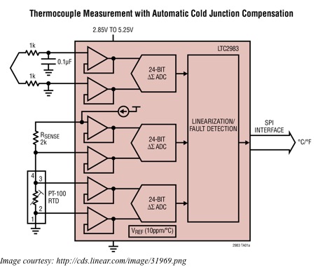
The LTC2983 carries within itself all the analog circuitry that different sensors need. It also has the necessary temperature measurement algorithms and data for linearization so that each sensor can measure temperature directly and the LTC2983 can output the results in degrees Centigrade. The IC makes it easy to handle all the challenges unique to diodes, thermistors, RTDs and thermocouples.

For example, a thermocouple will generate a voltage when there is a temperature difference between its tip and its cold junction – the tip touches the surface whose temperature is to be measured, while the cold junction is on the circuit board. Now, for an accurate measurement of the thermocouple temperature, you also require an accurate measurement of the temperature of the cold junction. A separate non-thermocouple temperature sensor, placed at the cold junction, usually does that.

With the LTC2983, you can connect diodes, RTDs or thermistors to measure the cold junction temperature. To convert the voltage output from the thermocouple into temperature, one has to solve a 14th order polynomial equation for both the voltage from the tip as well as from the cold junction. The advantage with the LTC2983 is that it has the required polynomials built into it for all the eight standard types of thermocouples – J, K, N, T, R, S and B – used in the industry. Therefore, not only does the LTC2983 measure the thermocouple output and the cold junction temperature, it also performs all the required calculations for reporting the thermocouple temperature in degrees Centigrade.

Thermocouples usually generate less than 100mV at full-scale output. Voltages at such low levels require the Analog to Digital Converter to have very low offset and noise. Furthermore, the reference voltage needed for the absolute voltage reading requires good accuracy and low drift. The 24-bit ADC within the LTC2983 has all these qualities – its noise and offset is below 1µV, and its reference voltage has a maximum drift of 10ppm/°C.

If the tip of the thermocouple is exposed to temperatures below that of the cold junction, the voltage output goes below the ground level. This complicates matters, as the circuitry requires an additional negative supply or circuitry that can shift the input level. The LTC2983 handles all this with a single ground-referenced supply, as it incorporates a front-end that can digitize signals below ground. In addition, the LTC2983 has high input impedance, low input currents and is able to accommodate external protection resistors and filtering capacitors.

What are WAN, LAN and DNS?

For those setting up a network at home to interconnect computers, it is important to know some technical jargon used in this field. Knowing the basics of home-networking makes it easier to read up and understand how actually computers talk to each other. Broadly speaking, computer communication is achieved in two ways – with wired networks and wireless networks. In this article, we will discuss wired networking.

Wired networking in the home refers to a number of devices connected together using a network of cables. Usually, this is accomplished with the help of a router, a central device, into which you plug in all the other devices using networking cables. The other end of the cable goes into a network port on the other devices. For this, all the other devices must have an individual networking port built into them. For all the end-devices that you want to connect to the router, you will need a free port on the router and a networking cable.

When you connect end-devices to a router, you are essentially creating a Local Area Network or LAN. A typical router has four LAN ports. Therefore, straight out of the box, it is able to host a network of four networking devices. If you want to add more to have a larger network, you must use a hub or a switch to add more LAN ports to your router. The router will identify all the end-devices connected to it with individual IP addresses. In general, a home router is able to handle 250 networking devices in total.

To allow the end-devices access to the Internet, a home router usually has a single WAN port, or Wide Area Network port. Some business routers sport two WAN ports, allowing users to connect to two separate Internet services. Physical separation and a different color distinguish a WAN port from the LAN ports. Via the WAN port, you can connect the router to an Internet source such as a broadband modem. You can also buy a combined router, which is a DSL/Cable modem and an Access Point (with a wireless router) bundled into a single package. in such a scenario, a telephone port (or a coaxial port) and a USB port typically replace the single WAN port, allowing connection of a telephone line, a cable and/or a wireless USB data card as Internet sources.

We name a website with a unique domain and host name to identify it. This is similar to the street number and the apartment name that identifies an address in real life. Since computers understand only IP addresses, DNS or Dynamic Name Servers translate the domain and host names to IP addresses transparently.

With DNS, a distributed database stores the name and address information of all the public hosts on the Internet. A hierarchy of special database servers stores this distributed database. Typing a web address into a Web-browser, which is the client, results in requests from a DNS resolver from the network operating system to the DNS server for determining the server’s IP address. DNS servers typically work in a hierarchy and, after locating the IP address, send it back to the resolver, thus completing the request over Internet Protocol.

Common Mode Signals and the Twisted Pair

People dealing with networking and instrumentation would have often come across the term “twisted pair”. This usually consists of two insulated wires twisted tightly together and is the most common method used to prevent noise on the wires from being carried into a device. This applies to most cables carrying signals related to communication on RS-485, RS-422, computer-network, video, audio and telephones systems. In technical terms, these signals are known as Common Mode Signals.

When you have a local common or ground, any signal with this as the reference and appearing on both the lines of a two-wire cable, with equal amplitude and in-phase, is called a Common Mode Signal. Therefore, if one of the wires is tied to the local common, the common mode signal will be non-existent. There are three ways such signals can arise – radiated signals can couple equally with both lines, the driver circuit may have an offset from the signal common or a ground differential may exist between the receiving and transmitting locations.

For an example, consider the three-phase Y-distribution lines of the AC power system. The neutral current of such a system flows through the earth and this can be 10-70% of the total neutral current flowing in the primary circuit. Ground differentials vary between locations and can be as much as several volts to several tens of volts. This differential can cause the three phases to be unbalanced by 0.2VRMS to 5VRMS.

Noise signals may appear in a cable for various reasons. For example, noise can be capacitive coupled from nearby electric fields, inductively from local magnetic fields, electromagnetically from radio signals or conductively from circuit path leakages. However, when you have a twisted pair line, it intercepts the coupled signal equally, making the incident signals appear only as common mode signals. You have a balanced twisted pair line if there is identical impedance from each line to the local common.

When driving audio signals across a pair of twisted wires, either wire has the same chance of being coupled to some unwanted signal or noise as its twisted partner. That means this common mode signal or unwanted signal appears equally on both wires. The audio circuitry is designed to reject this type of common mode signal and this characteristic is known as its CMRR or Common Mode Rejection Ratio, expressed in dB. Achieving circuit balancing is carried out in two ways – most commonly through impedance balancing and through differential balancing.

With impedance balancing, you can achieve better common mode signal (noise) rejection, as there is a balanced connection to ground. The simplest but most effective way is to use two matched resistors from each line to the common ground. The cable wires must also have the same diameter and resistance for the balancing to be most effective.

In differential balancing, the source equipment transmits the normal signal through one of the conductors of the twisted pair and a polarity-inverted signal through the other. Such differentially balanced or symmetrical lines offer the highest common mode rejection ratios, even though the principle remains the same as that of impedance balancing.