Category Archives: Guides

Solar Panels for Boats

Solar panels can easily be installed and utilized on boats for power. There is very little maintenance required to keep them in working condition and if properly installed, the solar panels should last 10 years or more.

The first decision is what kind of solar panels to buy. The most efficient option are mono-crystalline solar panels. Not only are they efficient, they are the most widely available. You might also consider using poly-crystalline panels which are slightly less efficient as the mono-crystalline type. If you have concerns about shade, you can buy the thin film solar panels.

Your next decision is where to install them on your boat. It is recommended that you install them high and aft on your boat, and in direct sunlight. One suggestion would be to install them maybe over the cabin or above the davits. The goal is to avoid installing them where the shadows might affect their performance. If shadows are an issue, consider installing them on a rail along the stern or over the bimini.

If your solar panels are shadowed, even just one complete row of cells, you will not be generating any power. The solution would be to either move the solar panels to a location that is not shadowed or to use a shade resistant amorphous solar panel.

Keep your solar panels operating at their maximum efficiency by wiping off any residue laying on the surface of the panel. Solar panels generally require little maintenance and are able to withstand the outdoors, so think about how you might be able to use them to power your boat.

How Do You Store Your Electronic Components?

Storing and retrieving a large number of electronic components like capacitors, resistors, LEDs, transistors, diodes, ICs etc. can be a daunting task not only because they are tiny but also because extreme temperature and humidity can deteriorate their performance. They also need careful handling as they are fragile and the tips can break easily.

In addition, electronic components need to be protected against static electricity.

To keep static electricity from damaging your sensitive electronic components, we recommend that you use sheets of anti-static foam. These foam sheets are easily cut to size to fit your storage containers.

A sheet of pink anti-static foam

A sheet of pink anti-static foam

There are a variety of container options to store electronic components safely. A range of molded ABS plastic boxes that can be side locked and stacked either vertically or horizontally are available. Each drawer has a number of compartments and can be labeled for easy identification. The various electronic components like resistors, capacitors etc need to be sorted and stored in these compartments in logical fashion. The drawers are easy to slide and can be pulled out / pushed in without much effort.

Ever wonder how the large electronic distributors store and retrieve their components? Automatic storage and retrieval systems make the job of storing and retrieving large numbers of electronic components easy and efficient. A typical construction has a vertical carousel in which a number of cameras are mounted on an endless chain activated by geared motors. The shelves are capable of rotating in either direction in a vertical plane. An electronic keypad facilitates calling the numbered carrier and bin / compartment. The system is equipped to store information about the location of code numbered electronic components in its memory. It can also be linked to a central computer for sharing of information for inventory control purposes. These automatic systems enable fast access of electronic components, instant stock update and save floor space, time, manpower and paper work involved in conventional storage systems.

AC vs DC – What is the Difference?

AC vs. DC

Electric current is the flow of electrons carrying electric charge. There are 2 types of electric current – direct (DC) and alternating (AC). In Direct Current the electron flow takes place only in one direction. A battery is a source of direct current. DC is widely used in many electronic circuits operating in low voltage levels.

In Alternating Current, both voltage and current alternate in direction back and forth following a sine wave pattern. The number of cycles per second, called the frequency, varies from 50 or 60 depending on the power system in a country. Alternating current is produced universally in power stations using AC generators. The AC theory is briefly described below.

A rotating coil in a magnetic field cuts the magnetic lines of force in two different directions during each half rotation in an AC generator. Thus the current produced travels alternately from left to right and then from right to left. When the coil is parallel to the magnetic lines of force, no current is generated. The alternating current so generated is collected by slip rings attached to the ends of the rotating coil and then transferred to an external circuit through metallic brushes.

Alternating current can be readily transmitted over long distances with minimum loss unlike DC. Any voltage drop along the way can be easily boosted using transformers. Also motors with high power can be designed using AC. Eddy current and radiation losses are the principal disadvantages of AC. 3 phase AC is generated in power stations, with each current out of phase by 120 deg to each other.

For a simple explanation about converters and inverters, visit this web page.

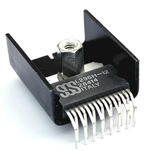
What is a heatsink?

When current flows through a resistor, part of the electrical energy is converted into heat that gets dissipated into the surroundings. If the heat generated is not quickly removed, it can permanently damage the electronic circuit. Heatsinks are devices that are capable of removing the heat from electronic devices and speedily dissipate it into surroundings.

Heatsinks can be passive or active devices. Passive heat sinks consist of fins made generally

Voltage Regulator in a Heatsink

Voltage Regulator in a Heatsink

of aluminum that provide a large surface area for heat dissipation. Active devices in addition have fans that circulate the air around the sink for faster removal of heat. The heat dissipation in a heatsink takes place principally through convection either natural or forced.

Heat transferred through convection is proportional to the temperature difference between the heatsink and the surroundings. The constant of proportionality is called convection coefficient. Mathematically, q = h x A x ∆t, where q is the heat dissipated by convection, h is the convection heat transfer coefficient, A is surface area and ∆t is the temperature difference between the heat sink and the surroundings. The coefficient h is a function of velocity of air circulating around the heatsink among other things. Thus higher the speed of air circulating around the heatsink faster is the heat dissipation.

Heatsinks are widely used for cooling electronic devices and the surrounding circuit like the CPU in a computer. With the need to make electronic devices more compact and powerful, the need to make high capacity heatsinks is increasing. Modern heatsinks are manufactured by extrusion, die casting, cold forging etc. Heat pipes have been used in heatsinks as they are lighter and more efficient compared to solid pipes of same size. Anodized aluminum is the most common material used in making heatsinks, although copper, silver and even gold have been used.

Desoldering – Why is it Necessary and How is it Done?

Soldered joints, if improperly done, may need to be ‘desoldered’ or the solder removed in order to resolder them. A poorly soldered joint can result in failure of the electrical circuit over a period of time. This can happen for a number of reasons. Low quality solder or failure to properly clean the surface before soldering or even lack of proper technique and corrosion of the joint due to leftover flux, movement (shake) of the joint before the solder has cooled may all cause a poor soldered joint.

There are other reasons you might need to desolder a joint. Desoldering and resoldering may also be required in order to replace a defective electronic component or if you are troubleshooting an electrical circuit.

One common method of desoldering is to use a desoldering pump which is a vacuum pump similar in operation to a bicycle pump in reverse. The spring loaded plunger breaks the solder and gets sucked away by the pump. Repeated operation of the pump may be required in order to completely desolder a joint, or you can also use the solder pump to take up the bulk of the flowing solder and finish up the job with solder wick. Either way works – the solder wick is more expenisve so you may want to use both if you have a large job. Be careful – the pump should be operated carefully so that no damage the PCB or the electronic components occurs.


A solder wick or braid is an alternative to desoldering pumps. Here the copper wick is placed over the joint and the solder is melted by means of soldering iron. The solder gradually flows into the wick and hence gets removed. The wick must be removed from the PCB before it cools down as otherwise it may damage the board.

How to Use an Analog Multimeter

How to use an Analog Multimeter
…it’s simpler than you think!

Multimeters are inexpensive and easy to operate, making them very popular. They are very commonly used as devices for electronics circuits testing. Multimeters are categorized into two different types – analog and digital. While the internal circuitry and operation of both are very different, their usage is more or less similar.

Analog multimeters have been in use for a long time and are very flexible in their operation. An analog multimeter can be used for testing a number of electronic components and parameters such as resistance, voltage, current, to name a few.

If you are using an analog multimeter, the first step is to switch the multimeter on. Next, the probes (or the leads) need to be inserted in to their correct positions. There can be a number of connections that can be made, and depending upon what is to be connected, the right positions should be determined. Care should be taken to not insert the leads in to a low current position, if high current is to be measured.

Next step is to set the center switch or knob to the required measurement type and the proper range. The range selected should be higher than the anticipated value. If the value is not known then the multimeter should be set to maximum and the range accordingly decreased afterwards. This ensures that the meter does not get overloaded. The range should be optimized for getting the best reading possible.

Once the reading has been taken, it is good practice to place the multimeter probes in to the voltage measurements sockets with the range set to maximum voltage. This ensures that even if the multimeter is accidentally connected, there is no damage to the multimeter or other electronic components of the circuit. Or if the reading is complete, then the multimeter can be switched off.

How to Read Capacitors

Capacitance Values – and How to Read Them

Capacitors are used in a wide range of electronic components and circuits. They form an integral part of electronics. The capacitance of capacitors is measured in a unit known as Farads, represented by the letter ‘F’. A capacitor that has higher capacitance can be used for storing more charge as compared to one with a smaller capacitance value.

One Farad is a very high value for capacitance and usually smaller units are used, namely pico farad, nano farad etc. And as the capacitors are physically very small in size, their capacitance needs to be identified with a code mentioned on the capacitor itself. The exception to this is electrolytic capacitors that are big enough to have the capacitance value written directly on them.

Ceramic and film capacitors usually have a coded value marked on them. If the value marked on them is a two-digit whole number, then the capacitance is equal to the value mentioned in pico Farads. Thus a code of “10” implies that the capacitance is equal to 10 pico farads.

A three-digit whole number includes the first two significant digits, and the third digit as the multiplier (indicating the number of zeroes), and gives the value in pico Farads. Thus a code of “104” means, 10 multiplied by 10,000, giving the capacitance as 100,000 pF or 0.1 uF.

If a decimal number is used as the code on the capacitor, then the capacitance is equal to value mentioned in micro Farads. For instance, “.1” mentioned on the capacitor would imply 0.1 uF.

Finally, a whole number followed by the alphabet ‘n’ means the capacitance is equal to value mentioned in nano Farads.

In addition to the capacitance, the code on these electronic components can also be used for indicating the tolerance, voltage, and temperature properties.

470pF 3000V Capacitor

470pF 3000V Capacitor

In the example above, the capacitor reads:

471M

3KV

The 471 is deciphered as 470pF; M=20% tolerance; 3KV=3,000V

Here are the codes for tolerance:

B +/- 0.1pF
C +/- 0.25pF
D +/- 0.5pF
E +/- 0.5%
F +/- 1%
G +/- 2%
H +/- 3%
J +/- 5%
K +/- 10%
M +/- 20%
N +/- 0.05%
P +100% ,-0%
Z +80%, -20%

Understanding Resistor Values

Resistors are available in a wide range of values, but if you observe carefully you will realize that certain values of these electronic components like 15k ohm and 33k ohm are easily available where as some values like 20k ohm and 40k ohm are hard to find. Let’s try and understand the logical reason behind this.

Take a hypothetical situation, where you make resistors every 10 ohm, thus giving you 10 ohm, 20 ohm, 30 ohm, etc. But once you reach the value of 1000 ohm, a difference of 10 ohm would hardly be noticeable as it is a very small value in comparison and making 1000 ohm, 1010 ohm, 1020 ohm and so on, would prove to be futile. In fact making such accurate resistors might prove to be very difficult.

Resistor

Resistor

Thus a acceptable range for these electronic components is one in which the (amount of the) step increases with the value. This is the logic that the resistor values are based upon, and they form a series following the exact pattern for every (multiple of) 10. There are two such series based on the above logic – the E6 series and the E12 series.

E6 series: Has six values per every multiple of ten with 20% tolerance. So the series goes like:10 ohm, 15 ohm, 22 ohm, 33 ohm, 47 ohm and so on, continuing to 100 ohm ,150 ohm, 220 ohm, 330 ohm with each step size (to the higher value) being higher than the last step size, and approximately half of the value.

E12 series: Has twelve values per every multiple of ten (10% tolerance). So the series goes like:10 ohm, 12 ohm, 15 ohm, 18 ohm, 22 ohm, 33 ohm, 39 ohm and so on, continuing to 100 ohm, 120 ohm, 150 ohm etc, thus it is nothing but the E6 series with an additional value in each gap.

E12 series is in common use for resistors and lets you choose values with 10% error margin, and proves to be accurate enough for most projects.