Category Archives: Guides

How to Select Voltage References

how to select voltage referencesSensing applications use Analog to Digital Converters and Digital to Analog Converters and the accuracy of their readings depends on the voltage reference used. Most often the voltage reference used are very simple components with only two or three pins. However, the performance of these references depends on several parameters and careful attention is necessary when selecting the proper one. Typically, applications use either a shunt or a series voltage reference.

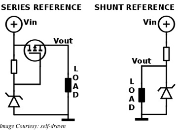
A series voltage reference is basically a high precision, low-current linear regulator. The load current comes through a series transistor positioned between the input voltage and an internal reference voltage. For the shunt voltage reference, a transistor placed parallel to the load shunts excess current to ground. As the series reference has to supply only the required load current, the shunt reference dissipates more power. The bias current of a shunt reference has to be greater than or equal to the maximum load current plus the minimum operating current of its internal reference.

In general, shunt references offer the user greater flexibility in handling higher input voltages and in creating floating or negative references. They also provide better power supply rejection but consume higher power. On the other hand, series references dissipate lower power and perform better for high-precision applications. The typical way of depicting the use of a shunt reference is by showing the symbol of a Zener diode.

Drift or variation of the reference voltage over temperature is a very important factor and has the units of parts-per-million per degree Celsius or ppm/°C. Most monolithic references use the bandgap reference as their base. Special circuitry is required to maintain drifts lower than 20 ppm/°C with the additional circuitry providing some form of curvature correction. Other types of references use a buried Zener diode voltage combined with the base-to-emitter voltage of a bipolar transistor to provide a stable reference voltage of about 7V. Both types have similar drift characteristics, but buried Zener types offer better noise performance.

All voltage references generate internal noise producing a dynamic error degrading the signal to noise ratio of a data converter. Device datasheets typically provide specifications separately for low and for high frequency noise in addition to the broadband noise in rms microvolts over the 10 Hz to 10 KHz bandwidth. You can reduce the broadband noise by adding a bypass capacitor.

Thermal cycling or change in temperature causes references to show thermal hysteresis. This appears as a shift in the reference voltage. Manufacturers define a thermal cycle as an excursion from room temperature to a minimum and a maximum temperature with a return to the room temperature. This is important as the reference may have to be soldered and this can induce shifts from the desired reference voltage.

Continuous operation may cause long-term stability issues resulting in a typical shift in the reference voltage. Manufacturers usually state the shift after six weeks or 1000 hours of continuous use. Since long-term stability is typically related logarithmically to time, the shift in reference voltage in the first 1000 hours provides a rough idea of the stability of the voltage reference over its life.

Common Mode Signals and the Twisted Pair

People dealing with networking and instrumentation would have often come across the term “twisted pair”. This usually consists of two insulated wires twisted tightly together and is the most common method used to prevent noise on the wires from being carried into a device. This applies to most cables carrying signals related to communication on RS-485, RS-422, computer-network, video, audio and telephones systems. In technical terms, these signals are known as Common Mode Signals.

When you have a local common or ground, any signal with this as the reference and appearing on both the lines of a two-wire cable, with equal amplitude and in-phase, is called a Common Mode Signal. Therefore, if one of the wires is tied to the local common, the common mode signal will be non-existent. There are three ways such signals can arise – radiated signals can couple equally with both lines, the driver circuit may have an offset from the signal common or a ground differential may exist between the receiving and transmitting locations.

For an example, consider the three-phase Y-distribution lines of the AC power system. The neutral current of such a system flows through the earth and this can be 10-70% of the total neutral current flowing in the primary circuit. Ground differentials vary between locations and can be as much as several volts to several tens of volts. This differential can cause the three phases to be unbalanced by 0.2VRMS to 5VRMS.

Noise signals may appear in a cable for various reasons. For example, noise can be capacitive coupled from nearby electric fields, inductively from local magnetic fields, electromagnetically from radio signals or conductively from circuit path leakages. However, when you have a twisted pair line, it intercepts the coupled signal equally, making the incident signals appear only as common mode signals. You have a balanced twisted pair line if there is identical impedance from each line to the local common.

When driving audio signals across a pair of twisted wires, either wire has the same chance of being coupled to some unwanted signal or noise as its twisted partner. That means this common mode signal or unwanted signal appears equally on both wires. The audio circuitry is designed to reject this type of common mode signal and this characteristic is known as its CMRR or Common Mode Rejection Ratio, expressed in dB. Achieving circuit balancing is carried out in two ways – most commonly through impedance balancing and through differential balancing.

With impedance balancing, you can achieve better common mode signal (noise) rejection, as there is a balanced connection to ground. The simplest but most effective way is to use two matched resistors from each line to the common ground. The cable wires must also have the same diameter and resistance for the balancing to be most effective.

In differential balancing, the source equipment transmits the normal signal through one of the conductors of the twisted pair and a polarity-inverted signal through the other. Such differentially balanced or symmetrical lines offer the highest common mode rejection ratios, even though the principle remains the same as that of impedance balancing.

How does an Android process sense motion?

The Android 4.4 Operating System from Google is able to track your motion in real-time. You can test this with the Google-map application when traveling – your current position as shown on the map will shift as you move. Although this was feature available earlier as well, Google has mandated that 4.4 version onwards, Android will be using this function in the background while it has turned the application processor off. Google has introduced this change to save battery life.

To comply with this mandate, manufacturers will now have to offload this function from the application processor and transfer it to a sensor hub. In anticipation of this mandate from Google, InvenSense has already transferred those functions into their patented DMP or Digital Motion Processor, which they have announced as their six-axis MEMS combo processor for an accelerometer and a gyroscope. Therefore, smart sensors will be providing the real-time contextual awareness functions in the background of your smartphone, while its screen is switched off.

This can be done in one of two ways. One of them may be to allow several new sensor functions to be run in a sensor hub. However, this has the disadvantage of adding cost to the product. A much better way, followed by InvenSense, is to include the processing within the sensor itself, which means smartening up the sensors. The MPU-8515 is a six-axis digital motion processor developed by InvenSense for this purpose.

Inside the MPU-6515, there is a three-axis gyroscope along with a three-axis accelerometer housed within the same package. With an enhanced version of their DMP built into their MPU, InvenSense is able to handle the specific functions that the Android operating system mandates running external to the application processor. With the MPU-6515, sensors can remain on for more time and supply more real-time data for location and context awareness yet reduce battery consumption.

In practice, the Android operating system shuts down the application processor when there is no activity input from the screen. It wakes up only when it receives a significant motion interrupt while rejecting false triggers to switch the application processor back on. Significant motions include pedometric functions such as detecting and counting steps while running in the background.

Processing information accurately when the application processor is turned off involves inertial location tracking. That requires processing rotation vectors involving six axes. The MPU-6515 does this by amalgamating the outputs of three axes from the gyroscope and three axes from the accelerometer sensors and buffering them periodically between the significant motion interrupts using a new batch mode.

The MPU-6515 can work in both modes – with a hub or in a hub less mode. This additional functionality is helpful for situations where the Android operating system has turned off both the application processor and the hub. Using this combo gyroscope and accelerometer chip with enhanced digital motion processor, InvenSense has been able to enhance its handling of contextual awareness for the Android operating system.

Manufacturers can easily use the MPU-6515, measuring a mere 3x3x0.9 mm, in smartphones, wearables, tablets and in devices for Internet of Things. Those using the earlier device from InvenSense, the MPU-6500 can easily replace the older chip as both are pin-compatible.

Let Raspberry Pi do your Calling and Answering

In certain projects or experiments where you are monitoring an entity such as temperature or pressure, it is impractical to be physically present for any length of time. However, it may be important for you to know when the measured entity breaches a high or a low set point. For example, if something is not working out as it should – say temperature or humidity too high – you may wish to start or control another activity rather quickly to compensate.

In such cases, the handy, credit card sized single board computer, the Raspberry Pi or RBPi can be of immense help. RBPi can call, sms or inform you via web-interface, in case things are tending to go beyond their limits. Although sms and web-interface work equally well, for cases that are more important a call gets more attention than the others do.

When receiving a call, you expect the other party to speak up. Programs such as eSpeak and Festival endow an RBPi with capabilities of synthesized speech. Both tools allow you to cache speech as wav-files. eSpeak is more adjustable and creates wav files a bit faster than Festival; however, their performance is similar. You can select any one of the programs depending on your preference and install it with a ‘sudo apt-get install …’ command.

For making calls, it is simpler to use a sip/voip based system. Here again, you can select between two capable tools – PJSIP or Linphone. Of the two, Linphone is difficult to include into an application script. PJSIP has a command line interface and provides a powerful api that you can use within your own sip-based project. However, you will need to download and compile it for Raspbian.

After compilation, you may find some echo or jitter when making normal calls to another phone. To get rid of these, you will need two other tools – sipcall and sipserv. Sipcall will help you to make a completely automated call to a specified number using a text to speech converter. That makes it very useful when using via bash-scripts. For example, you can ask it to check the state of a sensor and place a call if a critical threshold is reached. On the other hand, Sipserv is more like a service, where you make a call to query information and/or execute a command via phone. Of course, your sip-provider must support inbound DTMF. Both tools are available here, but you will need the pkg-config-package tool to compile them.

The original author has also created simple bash-scripts that can check the actual load and place a call if the load is found too high. For stopping/starting the service available, he has provided a simple configuration and a bash-script that you can use for Sipserv. Readme files and general info is available for the user. For more details, refer here.

Although the tools are rather ‘proof of concept’ than a final product, they work well. The author permits changes and extensions to his original work and invites suggestions on any improvements, more especially for the current sound problems of echo and jitter.

Integrate your Raspberry Pi to the Hackable Roomba

You do not find many robots in the consumer arena, unless it is the AVA 500, the telepresence robot from iRobot. Users can simply specify where they want AVA 500 to be and it automatically navigates to the destination without requiring any human intervention. It has advanced mapping technology combined with a real-time view of the environment. Another simpler consumer robot is Roomba, from the same company, iRobot.

iRobot has turned the highly successful Roomba 600 robot into a hackable Create 2 version. This is very useful for K12 and college level STEM education, because Create 2 can be programmed via a laptop, an onboard Arduino or a Raspberry Pi (RBPi). Although both AVA 500 and Roomba are Linux based, unlike the more sophisticated AVA 500, Roomba 600 was a modest, vacuuming robot, based on a simple Motorola HC12 micro-controller.

Create 2, the modified Roomba 600, is not meant for vacuuming, as iRobot has eliminated all the internal vacuuming equipment. That leaves Create 2 with plenty of space inside for adding custom hardware components. You can easily put in an RBPi there, using pre-programmed routines to control the bot. Other alternate methods of direct control are tethering Create 2 to a laptop via the serial Mini-Din port using a serial-to-USB cable.

Based on the original Roomba 600, Create 2 is a round, 3.58-Kilo robot, measuring 340 mm in diameter and 92 mm in height. The market has several models of the Roomba robot, but Roomba 600 is the cheapest. iRobot offers 3D printing files that help you in adding electronics and peripherals to Create 2. They provide instructions for replacing the bin with a cargo tray that you can 3D print. They also supply a faceplate drill template.

Rechargeable batteries on the Create 2 allow a three-hour run before needing a recharge. As with the original Roomba 600, Create 2 will also return to its charging dock when it is time for a recharge. Sensors, such as IR transceivers on Create 2 enable it to escape cul-de-sacs and move around obstacles.

To interface with the Motorola MCU and related components, Create 2 comes with a programming environment, the Roomba OI or Open Interface. With the Roomba OI, a user can program the behavior, sounds, movements and read its sensors. The OI provides several commands for the sensors, cleaning, song, actuator and mode settings.

RBPi Model A is the most suitable for controlling Create 2 as you can run it off the serial connector of the robot. Power requirements for the Model A and its camera are just within the headroom of the on-board thermal resettable fuse of Create 2. It is also possible to work with RBPi models A+, B or B+; however, you will have to power them independently.

The RBPi will need an SD card of at least 4GB, pre-installed with the Raspbian Linux. Other hardware that you will require are an RBPi camera board, a switching DCDC converter, a micro-USB male cable, a 5V to 3.3V level converter and a USB to Wi-Fi module. iRobot provides several programming samples and starter projects with varying levels of difficulty.

What is a Broadband Internet Connection?

To access the internet from homes, offices or mobile devices, internet services are necessary. This is offered in mainly four different forms – Digital Subscriber Line or DSL, cable, fiber-optic and satellite. All the above are commonly known as broadband services since they provide high access speeds compared to the old dial-up connection, which is the only non-broadband service. Although this is the cheapest way of connecting to the Internet, most users prefer faster connections such as provided by a broadband Internet connection.

The DSL connection makes use of unutilized telephone wires to provide Internet service. The speed of the connection varies with the distance of the user from the switching station – the speed will be slower the further away the user is.

A local provider of cable TV provides broadband Internet services through cable. Here, there will be several subscribers on a single service, sharing the bandwidth. The speed will vary with the number of users on the service at any specific time – decreasing as the number of connected users goes up. The speed is usually at its lowest at peak times, for example in the late evenings when many people will access the internet after the day’s work is over.

Fiber optics provides the fastest Internet connection and is the latest method. Since it is one of the newest methods, service areas are limited. In addition, laying fiber-optic cables under the ground is a time-taking task. Although the cost is comparable to that of both DSL and cable, the service provided by the fiber-cable is of a much faster connection.

Satellite services are one of the slowest forms of Internet connection and the most expensive. They are also notoriously complicated to set up and use. However, for people living in remote rural areas, a satellite broadband Internet service may be the only means of communication possible.

Broadband Internet services provide several advantages over more conventional means of accessing the Internet. DSL and cable connections are very easy to obtain and connect with the computer. The high speeds enable users to multitask while working on the Internet. For example, it is possible to surf the net while listening to music over the web.

At home as well as in the office, networking of several computers is made easier with a shared broadband connection. Both wireless as well as wired modems are available for this purpose.

Another trend recently introduced is the mobile broadband service. The modem offered is typically in the shape of a USB stick, only larger. It comprises a wireless device and a socket for the SIM card. When connected to the computer and supplied with the username and password, the wireless device searches for and connects to the transmissions of the service provider. Nowadays, with newer devices in the 4G or fourth generation, very high speeds are achievable.

One of the main advantages of broadband services is that it will not keep your phone lines engaged while you are surfing. This was the case with the old dial-up type of Internet service, where the user would not be able to make or receive telephone calls while connected to the Internet.

How Does Wireless Broadband Work?

High-speed Internet access is a necessity nowadays, and people are not satisfied with the slow dial-up access. Different forms of broadband Internet services are available that provide high-speed access. Access speed is usually measured by bit rate, which is the number of bits processed per unit of time. You are using a broadband Internet service if your data speed is or above 256 kbps (kilobits per second). Typical speed figures for broadband downloads can range from 1.5Mbps to 159Gbps. Therefore, broadband is an evolution over the original high-speed internet service, ISDN or Integrated Services Digital Network.

With the proliferation of mobile devices, there is increasing need for mobile broadband services that do not restrict movement with cables and telephone lines. This requirement has brought forth another contender – the wireless broadband Internet service. As its name suggests, you have high-speed access to the Internet without any cable or wires trailing your device. Consumers are increasingly demanding wireless Internet service, as they perceive its versatility and its potential for improving their productivity.

Wireless broadband service is available increasingly at home, in offices and even at the local groceries or coffee shop. Service providers are offering packaged Internet service deals that users can access wirelessly from any location within the coverage area of the service.

You generally connect to a wireless broadband Internet service through a wireless network. Setting up this arrangement of a broadband wireless network in your home or office requires several pieces of equipment – a wireless transceiver and a wireless router – all a one-time expenditure. In addition, you need to invest in a continual expenditure in the form of a broadband service. Without this broadband service, your broadband tools will not work.

The wireless devices and the broadband internet service together make up your wireless broadband network. When deployed, the network will transmit data from your broadband Internet connection via these wireless tools using a special wireless technology called Wi-Fi. Only Wi-Fi enabled devices will be able to connect to the Internet from anywhere inside the coverage area defined by the location of your wireless router.

Although Wireless broadband Internet service is popular and is increasingly being used in homes and offices, there is another wireless technology gaining ground – Wireless Internet service. With wireless broadband Internet service, you have a package deal that involves the broadband service that you have to subscribe to and the hardware for the wireless technology. On the other hand, wireless Internet service is intended for use in a much larger location outside the home or office, such as a college campus or the downtown area of a city.

The growth of cell phones has increased the popularity of wireless Internet connectivity. Cell phones now feature several mobile applications designed with advanced wireless technology. Therefore, mobile devices can now connect to a wireless broadband internet service via Wi-Fi or directly to the Internet via their own cellular phone networks.

GSM or Global Systems Mobile has introduced a technology for improving mobile connectivity – EDGE. Likewise, their competitor CDMA has introduced EVDO, which is significantly faster than EDGE. Another upcoming technology in this field is the WiMAX, which is expected to provide speeds in excess of 40Mbps by the end of next year.

Rapiro the Customizable Robot with Raspberry Pi

If you have a kid aged 15 or above with a Raspberry Pi and he is clueless about his next project, Rapiro, the customizable robot may be very suitable for him. Designed for the tiny credit card sized single board computer, the Raspberry Pi or RBPi, Rapiro is a humanoid robot kit. It is an affordable kit and is very easy to assemble, needing only two screwdrivers. With an Arduino compatible controller board, the kit comes with 12 servomotors and limitless possibilities.

Even if you are not a programmer, Rapiro is easy to assemble and set up. The assembly instructions are simple and given in a step-by-step method, so anyone can follow them. Rapiro’s controller board is pre-programmed, so that Rapiro will come alive as soon as you have finished assembling it. However, if you are a programmer, you could make Rapiro sweep your desk or have him dance to a tune. For this, you will need to use the Arduino IDE to reprogram Rapiro.

Rapiro is highly customizable. Limited only by your imagination and the sensors you have at hand, simply install the RBPi board and go on expanding the capabilities of Rapiro. For example, you can add image recognition, Bluetooth, Wi-Fi and anything else you can think of to make Rapiro livelier.

Rapiro has 12 servomotors to make it move. There is one servomotor in its neck, one in its waist, two each in its feet and three each in its two arms. There are six servos in its neck, waist and feet have a torque of 2.5kgf-cm each. The servos in its two arms have a torque of 1.5kgf-cm each. The operating speed for all the servos is 0.12sec/60° and the maximum angle they can move through is 180°.

You can program it’s eyes to give its face a full and colorful expression. Its eyes are made of bright LEDs, which can be programmed for different colors as they are of the RGB type. Plastic parts of Rapiro suit both models of RBPi – A and B. With small modifications, Rapiro can accommodate RBPi model B+ as well.

Rapiro’s controller board is very similar to an Arduino board and you can program it using the Arduino IDE. Anyone familiar with C++ development environment can use the Arduino IDE to program the 8-bit AVR based micro-controller on board Rapiro. However, that does not mean only those with programming skills can work with Rapiro – beginners can also learn how to program.

Once you have installed RBPi inside Rapiro, you can make it do more functions. With RBPi, you can use your favorite programming language on Linux to program Rapiro. For example, you could program Rapiro to watch over your home while you are away and to keep in touch by sending you text messages over Wi-Fi. You could have Rapiro acting as a security robot for your house if you give it vision by installing a camera module.

Rapiro requires five AA Ni-MH batteries to function. You can replace this with an AC adapter also. For transferring data, you will also require a USB cable to connect Rapiro to your PC.

How Do RCDs Protect?

If you touch something electrically live, such as a bare wire, chances are that you will receive an electrical shock that may even be fatal. An RCD or a Residual Current Device protects you from this danger, offering a level of personal protection not provided by circuit breakers and fuses. The RCD, being a sensitive safety device, automatically switches off electricity when it senses an earth fault.

Earth faults are associated with the risks of electrocution and fire. Such faults happen, for example, when you accidentally touch a faulty appliance or an exposed live wire, causing electric current to flow to earth. Outdoors, such faults may be the result of a lawn mower cutting through the supply cable.

When an RCD is protecting a circuit, it constantly monitors the electric current flowing through the different paths. The RCD switches off the circuit very quickly as soon as it detects an unusual electrical activity such as current flowing through the body of a person who has accidentally touched a live part. This reduces the risk of serious injury or death.

Using RCDs is an effective way of protecting oneself from electric shock in potentially dangerous environments such as gardens and bathrooms. To be as safe as possible, the RCD to be used must be chosen carefully from among fixed, socket-outlet and portable types.

Fixed RCDs are usually installed in commercial and industrial places at the consumer unit or fuse box. Typically, they provide protection to individual or groups of circuits. As all wiring, sockets and connected appliances on a circuit remain protected by the fixed RCD, it offers the highest level of protection.

Special socket-outlets can have RCDs built into them and you can use them in place of standard socket-outlets. This type of RCD will protect only the person who is in contact with the equipment plugged into the special socket-outlet, including the equipment’s lead.

You can plug portable RCDs into any standard socket-outlet. Just like the socket-outlet RCDs, It will protect any person who is using a device (including its lead) plugged into the portable RCD. This is a very useful device when neither the fixed nor the socket outlet RCDs are available.

Reliability of an RCD increases when tested regularly. Apart from reducing the risk of electric shock to you and your family, fixed RCDs will also defend your home against the risk of fire caused by an appliance or faulty wiring.

Although protection by using an RCD does reduce the risk of injury or death from electric shock, it does not mean that you should not be careful. Get your home wiring checked every ten years to ensure the safety of your home and your family. A registered electrician should immediately attend to any fault in the wiring or an appliance.

Be aware that if the RCD does not shut off the electricity supply even after you have held the test button for a long time, the RCD is most likely not functioning. Have it replaced or take advice from a registered electrician.

How to Measure Large DC Currents Accurately?

The market has several instruments for accurately measuring small DC currents, say up to 3A. You can also find some devices that can measure DC currents that extend beyond 50A with good accuracy. Large currents are common in photovoltaic renewable energy installations, grid energy storage, electric vehicles, to name a few. Usually, it is a common necessity for such systems to be able to predict accurately the state of charge or SOC of the associated energy storage batteries.

Usually, systems for current or charge measurements are designed to include built-in data acquisition modules such as ADCs or analog to digital converters, filters and suitable amplifiers. The arrangement is typically that of a current sensor followed by a filter/amplifier and finally an ADC. The current sensor senses the current a circuit for converting the output into a usable form such as voltage, typically follows it. The signal requires filtering to reduce the radio frequency and electromagnetic interferences. The cleaned signal may have to be amplified before being digitized. Current data samples multiplied by the appropriate time interval are accumulated for charge values.

Two sensor technologies are commonly used for measurement of large currents. The first of these techniques measures the voltage drop across a resistor (also called a current shunt) that carries the current to be measured. The voltage drop follows Ohm’s law and equals the product of the current times the resistance.

Large DC currents may cause power bus bars and cables to dissipate significant amounts of heat. As a thumb rule, designers of power installations strive to achieve less than 1% power loss from the wiring, including bus bars and heavy cables. For example, an offline storage system of batteries with output of 1KV and 1KA supplies power at 1MW. Although the dissipation of a 50W shunt is insignificant at 0.005%, the power cables and bus bars may dissipate heat upwards of several KW.

To put things in perspective, designers go by 1W per µOhm at 1KA, therefore, for a shunt with 10 µOhm resistance, a continuous current of 1KA passing through it will heat it up to 10W. Alternately, copper wire, with a diameter of one-inch, will be dissipating 12-14W of heat at 1KA for each foot, since the resistance of the wire is about 10 µOhm per foot, after correcting for resistance increase due to heating.

The second technology senses the magnetic field encircling the current carrying conductor. The device for sensing the current is generally known as the Hall-Effect current sensor. Usually, the magnetic field around the current carrying conductor is concentrated in a magnetic core, which has a thin slot and the Hall element resides here. The magnetic field is thus perpendicular to the plane of the Hall element, while the magnetic core makes it nearly uniform. Energizing the Hall element with an exciting current makes it produce a voltage proportional to the magnetic field in the core and the exciting current. This voltage, suitably amplified and filtered, is presented to the ADC.

One advantage of the second technique using Hall elements is the isolation between the current carrying conductor and the measuring electronics. Since the coupling is only magnetic, the current carrying conductor may have very high voltage potentials, which do not affect the current measuring elements.