Category Archives: Guides

How do Piezomotors Work?

Voltage applied to a piezoelectric material causes it to change its shape very minutely. Piezomotors such as Piezo LEGS are ceramic actuators that have four legs as its motors. These are designed cleverly such that the applied voltage can either elongate the legs or bend them sideways. It is also possible to synchronize the movement of each pair of its four legs such that it begins to walk just as an animal would – step by step. While walking, the legs can also stop at any instance on a nanometer level. The driving rod produces direct friction coupling with the legs. That means piezomotors can operate without any mechanical play or backlash. The direct drive, apart from providing full force, also offers power-off locking that does not require any power consumption.

However, the friction coupling between the drive rod and the internal piezo actuator legs does not allow counting the steps or knowing the position of the legs accurately. When they are under constant load, the legs face a certain vibration between the steps. As the load or temperature varies, so do the vibrations. Therefore, separate position sensors are required to know the accurate position of the legs of a piezomotor.

Piezomotors can move extremely slowly. When running in a closed loop system, you can make them achieve a continuous smooth motion at speeds under 1µm/s or 0.001mm/s. Since the speed of a motor depends on its step length and step frequency, a typical linear piezomotor is limited to a maximum speed of 10-15mm/s. In reality, the speed depends on both the external loads and temperature. Therefore, to run the motor at constant speed, you must have a closed loop controller.

Compared to conventional motors, piezomotors are very energy efficient. For example, when in a hold position, piezomotors do not consume any power. They also do not draw peak currents while starting or stopping. Power consumption of such motors is not dependent on inertia. That means the motor will consume the same amount of power under different external torque/load. When operated with a low duty cycle and for point-to-point applications, piezomotors provide excellent battery life.

Just as in regular stepper motors, one can define holding force and stalling force for piezomotors as well. While running, the highest load that the piezomotor can hold dynamically without slipping is called its stalling force. When powered down, the motor is able to hold a load statically and the maximum load that it can statically hold without slipping back is called its holding force. In general, the holding force of a piezomotor is about ten percent higher than its stalling force.

Although the operating principle of a piezomotor is very similar to walking, it can walk with full steps, reduced steps and it can even do micro stepping. Usually, the drive rod or disc will engage with the two or more actuator legs to move them forward and release. Then it will engage with a second set of legs to move them forward. This cycle repeats as long as the motor walks. Therefore, it is always possible to divide the full step into several smaller steps – also called micro stepping.

Why Is Thermally Conducting Paste Used?

No matter how highly polished a surface may seem, when seen under a microscope it will have some irregularities. When two such metal surfaces are put together, air within the irregularities prevents heat from flowing efficiently from one metal to the other. A heat sink is usually placed on a micro-controller to remove the heat generated within the CPU. However, this arrangement will not work in the way desired unless some filler material is used to replace the air in the gaps in the interface between an IC and its heat sink. Such filler materials are usually Thermal Interface Materials or TIMs and generally called as thermally conducting paste.

Thermal pastes are semi-solid materials with very high heat conducting properties. These are placed between two surfaces, usually between a CPU/GPU and its heat sink, to allow better heat conduction between the two. Irregularities on the two surfaces may trap air between them, leading to a loss in the performance of the heat sink, as air is a very poor conductor of heat. TIM, being more than 100 times a better conductor of heat compared to air, improves the performance of the heat sink. However, the heat conducting property of thermal paste is not as good as Aluminum (heat sink material) or Copper (IC material), and a thick layer of TIM might actually hinder the ability of the heat sink to conduct heat properly.

A magnified view of the cross-section of two mating surfaces shows the microscopic imperfections that can trap air as in a pocket. TIM would fill-in these areas, replacing air. If you could have two perfectly smooth and flat surfaces, thermal paste would not be required to aid in heat transfer. However, that being impossible to achieve, thermal paste is necessary to improve the flow of heat. Depending on the application, you could use one of three types of thermal pastes – Silicon based, Ceramic based or Metal based.

Silicon based TIMs are generally used in cooling kits. These are commonly known as thermal pads and stock heat sinks use them freely. However, other pastes have better heat conducting properties.

When you need a paste that can also isolate electrically – Ceramic-based TIMs are hard to beat. They consist of a thermally conductive paste with plenty of tiny ceramic particles, which prevent flow of electricity. Although not as good as the Metal based TIMs, the difference is only minimal.

Metal-based TIMs are the most popular. These have the best performance characteristics, which comes from the innumerable tiny metal particles present in the high thermally conducting paste. However, this paste has a disadvantage that it can also conduct electricity.

Apart from the above three types of TIMs, there are also thermal epoxies. Although these function in a manner similar to the thermal pastes described, they possess an additional property – they can attach the heat sink permanently. Therefore, thermal epoxies must not be used when you need to get the heat sink off an IC. In case you have to separate a heat sink from an IC bonded together with thermal epoxy, the best procedure is to place the assembly in a freezer. The cold makes the epoxy brittle and it comes off easily.

Demystifying Power over Ethernet

Power over Ethernet or POE is an upcoming technology and most information available on the subject is either outdated or creates a lot of conflict. That puts off people wanting to use this new technology. Some misconceptions common to POE is discussed here.

POE leads to compatibility problems. In the early days of POE, several proprietary and home-brewed schemes were used to transfer power over networking cables. However, the standard IEEE 802.3af is now universally adopted for POE. That means compatibility between all modern equipment using POE is assured.

To use POE, one needs electrical knowhow. That was true of early implementation involving careful design. However, with IEEE802.3af, the design of POE ensures reliable operation in all configurations that is possible with the regular implementation of Ethernet. When the user has set up the network to work as normal, the equipment takes automatic care of delivery of power.

Special wiring is required for POE. This is not true. You can use the same cabling as used for regular Ethernet networks – RJ45 style of connectors with Cat6 and Cat 5e cabling. Both regular as well as POE-enabled local area networks can use the same connectors and wiring.

POE forces power into the device. This is a common misconception. Usually, manufacturers quote the maximum power ratings and the device draws only the power it needs. For example, if you plug in a 5W device into a socket capable of delivering 15W maximum, the power consumption is only 5W and there is no loss of 10W somewhere. Any electrical load will draw only the power it uses and no more.

The POE standard 802.3af is meant for network devices that draw around 13W of electrical power. However, there are devices in the market with POE that require a little more than 13W. Usually, these devices are proprietary and such high-power POE systems are not always compatible with devices complying with 802.3af POE.

The latest POE standard deals with such devices. This new standard IEEE 802.3at is called POE Plus and it handles double the electrical power – devices that can handle up to 25.5W.

Injectors and switches compatible to POE Plus can recognize any normal POE devices plugged into them and enable them as normal. Conversely, any POE Plus powered device plugged into POE injectors or switches are designed to restrict the amount of power they use.

The new standard 802.3at has scope for power budgeting. POE Plus devices can communicate with each other and simultaneously negotiate the allowance of electrical power. That means you can POE-power a more complete range of network equipment. This can include heaters and blowers, along with multichannel wireless access points.

However, both standards 802.3af and 802.3at coexist with each other and POE Plus does not replace POE. There are still many users of 802.3af for powering Power over Ethernet devices.

Most network cables utilizing Cat 6 or Cat 5e are made of eight wires arranged as four twisted pairs. Ethernet cables such as 10 and 100BASE-T use two of these pairs as data pairs for sending information. The balance two pairs, known as the spare pairs, remain unused. POE uses either the two data pairs or the two unused pairs at 48V to transfer power.

SSD, Magnetic or Hybrid Drives

Earlier, when we did not have much of a choice, PC storage options were limited to the largest capacity hard disk drive one could afford. Those days are long gone and today the average customer has to juggle between selecting different types of storage media apart from their capacity. Although it is fairly important to select the most optimum storage medium for a specific application, each of the drive types has their own advantages and disadvantages.

Magnetic hard disk drives have long been the default storage component for both desktop and laptop computers. Although the latest magnetic drives are very much advanced and better performing compared to their brethren from yesteryears, their underlying technology has remained mostly unchanged. Magnetic hard drives essentially consist of stiff magnetic platters rotating at high speeds paired with read/write heads travelling over their surface to retrieve or record data.

Magnetic hard disk drive technology is mature. Manufacturers now make highly reliable drives that users can purchase at much lower prices as compared with other storage options – most magnetic hard drives cost only a few cents per gigabyte. Moreover, they are available in relatively high capacities, going up to 4TB. Modern magnetic hard drives connect via the SATA or Serial ATA interface and do not require any special software for the operating system to recognize them. In short, magnetic hard disk drives are dirt-cheap, simple to operate and spacious.

However, the disadvantage with magnetic hard disk drives is their low storage or retrieval speeds compared to the SSDs and Hybrid products. The read and write speed depends on how fast the platter rotates – a 7200-RPM drive is faster than a 5400-RPM drive, but both are significantly slower than SSDs or even hybrid drives.

If you are just an average PC user sticking mostly to using mail, browsing the Web, and some amount of document editing, a standard magnetic hard disk drive should serve you fine.

SSDs or Solid State Drives are so called because unlike the magnetic drives, they do not have any moving parts – they are typically nonvolatile NAND flash memory. Although most SSDs connect via the SATA interface, there are PCI Express-based SSDs that offer ultrahigh-performances. SSDs store data and file just as any other drive does.

Since SSDs do not have any moving parts, they can operate at blazing speeds such as 500MB per second on average accessing data in just a few milliseconds. Compare this with the speed of a magnetic hard disk – 200MBps with access times just a shade below 8ms. In short, with SSDs you have a much snappier and a much more responsive system. With SSDs, everything is faster – boot times, application launch times and file-transfer speeds.

Without moving parts, SSDs are not susceptible to damage or degradation due to movement or vibrations. The two disadvantages with SSDs are their cost per gigabyte and their read/write life. At present, they cost about $1 per gigabyte.

Manufacturers offer Hybrid drives as a go-between. These are mostly magnetic hard drives with some SSD thrown in. The most frequently accessed data is stored in the SSD. That makes for high speed while the cost is kept low.

XMP-1 the Raspberry Pi Robot

XMP-1 the Raspberry Pi Robot
The inexpensive, credit card sized single board computer, the Raspberry Pi or RBPi, can be teamed up with another inexpensive, credit card sized processor platform, the XMOS startKIT. The duo presents the unique possibility for DIY enthusiasts to construct robotics applications. An additional incentive – almost no soldering required.

The XMOS StartKit comes with an XMOS processor chip that has multiple XMOS cores. You can program these cores directly in C. Multiple programs will run in parallel within the XMOS cores, at high speeds and without jitter. That is exactly what the robotics applications ideally require.

The combination of the RBPi and the XMOS startKIT makes a simple mobile platform that its designer Shabaz chooses to call as XMP-1 – the XMOS Mobile Platform, version 1. Using only simple tools such as pliers, wire-cutters and a screwdriver, XMP-1 involves only low-cost off-the-shelf standard hardware. It is flexible enough to allow addition of more sensors and programming to make it more versatile than it is at present. The XMOS board communicates with the RBPi via the Serial Peripheral Interface or SPI and you can control the XMP-1 from a web browser.

Although XMP-1 can move at quite a high speed, it is preferable to keep its speed low when it is being taught a new route. The console output and the browser controls are available on the display on the web browser to generate keep-alive and status messages to help you see what is happening. Shabaz has recorded this project in three parts, the first of which deals with programming the XMP-1 that has no sensors. In part two, Shabaz conducts more XMOS startKIT experiments. These serve to establish the process of high-speed SPI communication between the XMOS startKIT board and the RBPi.

You will be able to get the XMP-1 up and running, if you simply take the code, compile it and plug it into the flash on the XMOS startKIT board and the RBPi. However, this project is useful to all types of enthusiasts apart from those only interested in constructing and using XMP-1. For example, on the site, you will get adequate help in the XMP-1 hardware assembly, controlling hardware using RBPi and using a web browser to do it from a remote location. The site is very informative for those who are new to the XMOS startKIT.

The RBPi is connected to the network via an 802.11 Wi-Fi USB adapter and handles all network activity. A small web server running on the RBPi provides feedback to the user via a web browser. The RBPi also transfers the motor control speeds it receives from the user over to the XMOS startKIT board via the Serial Peripheral Interface. In turn, the XMOS startKIT feeds the motors with the correct Pulse Width Modulation or PWM signals.

Based on these input signals, the hobby servomotors operate to allow the XMP-1 to run at varying speeds in a straight line or to take a turn. Usually the servomotors rotate to less than a complete revolution – within a range of nearly 180-degrees. The output shaft is connected to linkages that make the wheels turn a full right, a full left or anything in-between.

How Good Are Hydrostatic Drives?

Wherever a means of power transmission and variable speed are required, we typically think of using mechanical and electrical variable-speed drives and gear-type transmissions. However, there exists another equally excellent means of transmitting power, and that is through hydrostatic drives. While offering a fast response, hydraulic drives can maintain precise speed under varying loads all the while allowing infinitely variable speed control from zero to maximum.

Gear transmission systems usually have a discontinuous power curve with peaks and valleys. For increasing available torque, you need to shift gears. Hydraulic drives can overcome both these shortcomings. However, despite their superior performance, hydrostatics have a major drawback – higher cost compared to their mechanical counterparts.

However, manufacturers are driving down the economics of using hydrostatic drives. They are producing smaller and lighter packages, while boosting performance levels and offering advanced electronic controls. Many applications now prefer to use hydrostatics to other types of drives.

Hydrostatic drives have several advantages, the most significant being – a basic hydrostatic transmission is an entire hydraulic system. The simple package contains all the required controls, the motor and the pump included. The single unit provides all the advantages of a conventional hydraulic system – ability to be installed without damage; easy controllability; an entirely stepless adjustment of speed, torque and power; with smooth and controllable acceleration. All this comes with the simple convenience of a single-package procurement and installation.

Earlier, hydrostatic transmissions were limited to low-cost applications such as garden tractors and farm equipment. However, with improved designs, especially in control systems, hydrostatic transmissions are now suitable for a wide variety of applications.

This has resulted in the use of light-duty units of less than 20HP being used on equipment such as small machine tools, maintenance equipment for golf courses and lawn tractors. Medium-duty units of 25-50HP are used on vehicles such as harvesters, trenchers and steer loaders. Agricultural and large constructional equipment mostly use the heavy -duty transmission equipment rated for 60HP and above.

The increasing attractiveness of hydrostatic transmission is partly due to the improved design of motors and pumps that result in higher flow and pressure ratings in more compact packages. For example, where earlier pumps could deliver only 0.125-gpm flow for every pound of pump, current pumps can deliver more than 0.5gpm/lb., representing a four-fold increase. Similarly, where older motors could provide only about 0.5HP/lb., newer motors offer 2.5HP/lb. with ease.

Today, you can have hydrostatic transmissions with at least three standards of output performance – Variable-power/Variable-torque, Variable-power/Constant-torque and Constant-power/Variable-torque. Additionally, you can select hydrostatic drive configurations such as close-coupled or split-coupled. The transmission size is specified by corner horsepower of the work function. You obtain corner horsepower by multiplying the maximum force required with the maximum speed requirement, although you may never require these two conditions simultaneously.

Earlier control capabilities of hydrostatic transmissions were limited to simple remote electrical actuators. Today, they have advanced to packages offering complete optimization of the machine performance.

Fuel savings and increased productivity make hydrostatic proportional controls economical to use in most traction drives and propel systems, although they may not be economical for every application.

What are Leadless Packages?

Electronic components, especially semiconductors have undergone a dramatic transformation over the past few decades. Starting from the through-hole packages, semiconductors evolved into the surface mount packaging, which is the default today. With the increase in packaging density, surface mount packaging is now limited to passive components mostly, while semiconductors are moving towards current technologies involving leadless packaging.

Modern technologies involve leadless packaging such as dual/quad flats with no leads (DFN/QFN), Ball Grid Arrays or BGAs and Chip Scale Packaging or CSP. Such innovative technologies are allowing the semiconductor industry to exploit the successive IC processing shrink and achieve product performances, which were thought impossible earlier

For example, consider a simple three-pin discrete device such as a MOSFET, typically used as a switching device that can conduct currents ranging from 0.1A to more than 100A at voltages surpassing 1000V. Applications as diverse as motor controls to battery management use MOSFETs.

Leadless packaging makes discrete devices more attractive because of the assembly efficiencies involved that makes them friendlier to the environment. Although several leadless solutions are possible for packaging MOSFETs – BGAs, CSPs and DFN/QFN – the governing factor here is mainly the market price pressure. Substrate costs may be expensive, making package material sets undesirable for BGA packaging. Moreover, capital expenditure required to changeover to full production with new packaging types such as BGAs and CSPs may increase the per-unit cost.

Consequently, BGA and CSP packaging is limited to discrete semiconductor applications where the average selling price is of a secondary consideration over more important parameters such as performance. At present, the traditional surface mount packages are being replaced by the more cost-effective alternatives leadless package solutions such as the DFN and QFN.

The manufacturing steps for a typical DFN package consists of six key processes. A silicon die is attached to a copper alloy or similar leadframe using a highly conductive epoxy resin. The package pads are then attached to the silicon die using wirebonds of aluminum or gold. The silicon and leadframe package is then hermetically sealed with a mold of a halogen-free compound. Sawing the molded lead frame yields the finished package product.

Leadless packages offer several advantages. They utilize the available board-space more efficiently, while improving the thermal performance of the device. For example, the SOT23 package, being one of the most widely used packages of the semiconductor industry, has a silicon-to-footprint ratio of 23%, while it occupies 8mm2 space on the printed circuit board. Comparatively, The DFN2020 package has a silicon-to-footprint ratio of 42%, which is nearly double that of the SOT23, while it occupies only 4mm2 space on the PCB. This leads to huge cost benefits to the manufacturing industry, while simultaneously increasing the electrical performance of the application.

The DFN package has a highly conductive copper alloy pad for the die, which is exposed to the outside of the package to be soldered. This larger area of contact between the DFN package and the printed circuit board results in a very low thermal impedance between the junction and the leads. This ensures not only a reliable contact, but also a higher thermal efficiency as compared to typical surface mount packages.

RemotePi: An Intelligent Infrared Remote Controlled Power Switch for the Raspberry Pi

When you have built a mediacenter system using the tiny single board computer, the Raspberry Pi or the RBPi, there is usually a hand-held infrared remote to manipulate the various controls. However, using the remote to switch off/on the mediacenter system does not switch the RBPi. Adding a RemotePi board lets you switch on/off the power of the RBPi safely with the remote or a push button.
There are two versions of the RemotePi board – one that fits the RBPi Models A+ or B+, and another that fits RBPi Models A or B. Although electrically similar, RBPi Models A+/B+ are different from Models A/B – the mounting holes and connectors are differently placed. Therefore, you must select the RemotePi board to fit your current RBPi model.

Additionally, the RemotePi board comes in two variants. The first has the IR receiver and LED integrated on it, while the second variant sports an external IR receiver and LED connected by a cable. The second variant is useful when you want to mount the RBPi and RemotePi out of sight, leaving only the IR receiver and LED visible for the users.

The RemotePi works by re-routing the power to the RBPi, instead of feeding it directly. On the board, a micro-controller manages the power line to the RBPi. Depending on the command received from the push button on the board or the infrared remote control, the micro-controller switches power on or off for the RBPi.

However, when switching off the power to the RBPi, RemotePi does not cut off the power immediately. Instead, it sends a notification to the RBPi via a signal on its GPIO port. The RBPi monitors this signal on the GPIO port continuously via a script running in the background. Once triggered, the script initiates a clean shutdown of the OS and thereby, prevents data corruption. Once the shutdown is successful, RemotePi then proceeds to cut off the power completely to the RBPi.

When the RemotePi has to switch power to the RBPi from an infrared remote control, you must teach the unit to recognize the type and button preferred. For this, you let the RemotePi enter a learning mode and then point your remote control towards the infrared receiver on the board. Now press the preferred button on the remote you would like to use in future to control power to the RBPi and the RemotePi will remember the button. For using a different remote or button, simply repeat the process.

Another feature of the RemotePi is that you can teach it to use one button to power off the RBPi and use another to switch the power back on. Apart from controlling power, the RemotePi board will forward any received infrared signal to the RBPi. Therefore, you can use the remote control for the mediacenter as well as use LIRC for the RBPi.

RemotePi prevents data corruption on the RBPi with sudden power outages. Additionally, you can reboot the RBPi to clear memory leaks or for automatic updates. It does not occupy a USB port and is totally compatible with the simple GPIO IR receiver.

Add Bluetooth to any speaker

using bluetooth on any speakerMany of us have old unused powered speakers stashed away somewhere. Even if they were to be used, long snaking wires would have to be laid, depending on how far away they were to be placed from the amplifier. In this era of Bluetooth, we are spoiled by the ease with which we can connect – without wires. In fact, Bluetooth allows us to connect not only two phones, but also computers, mice, keyboards, tablets, headphones, fitness trackers and so many more gadgets. However, Bluetooth audio remains the most popular application among all the above.

Bluetooth audio allows you to pair a speaker or speakers with any device, such as a phone, computer, tablet or any other, so that you have an audio connection – sans wires. Different types of Bluetooth speakers are available in the market. However, good Bluetooth speakers are quite expensive. The only advantage with these wireless Bluetooth speakers is that they will not be tethered by wires – their performance however, is not going to improve.

Therefore, if you have old speakers that still perform very well, upgrading them to work without wires will be worth the small amount of expenditure required to add Bluetooth to them. Once installed, the Bluetooth receivers in your speakers will pair with any Bluetooth enabled device. This will enable you to stream any audio from anywhere to your speakers.

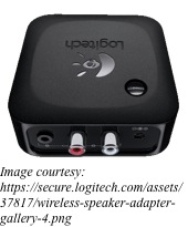
Depending on your needs, shop for the right type of Bluetooth receivers from sites such as Amazon, eBay and others. Some have optical audio connection, while others come with RCA plugs for the left and right channels. Almost all will have an LED that lights up when the unit is paired to a device. The units run on 5V, so a USB power supply will do, while output is taken through a 3.5mm stereo jack.

Setup is simple – connect the Bluetooth receiver’s audio out to the audio cable of your speaker, or to its auxiliary input, if the speaker has them. Next, power up the unit and now all that is left is to pair the unit with a Bluetooth device.

As soon as you plug in the power to the receiver, it will start broadcasting its identifier. Open the Bluetooth settings on the device you prefer and connect. If you have a low-end device, only one pair can remain connected at a time. To switch sources, you will have to disconnect the current pair first before pairing another. Some high-end devices can store up to eight different audio sources, allowing easy switching.

The sound quality of an audio system depends primarily on the quality of the source and then on the quality of the amplifier and speaker combination. Addition of the Bluetooth receiver in this chain does not detract much from the listening pleasure. In fact, you will hardly notice any difference between Bluetooth streaming audio wirelessly and speakers connected directly with wires. The advantage with Bluetooth connection is that you can place your speakers more than 30ft away from the source.

Therefore, if you have a pair of powered speakers lying around unused, you can upgrade them with Bluetooth. You will be surprised at how much better they sound compared to the tinny sound from your mobile.

Versatile Chip to Convert Temperature to Bits Directly

LTC2983One of the most fundamental aspects of our lives is temperature. As yet, measuring temperature accurately is difficult. Galileo was possibly the first person to have invented a thermometer that could measure changes in temperature. Two hundred years after Galileo, Seebeck discovered the principle of thermocouples – a device that generates a tiny voltage related to temperature gradients in dissimilar metals. Today, we use many elements such as semiconductor elements and temperature dependent resistive elements for measuring temperature electrically.
Most temperature measuring elements are analog devices. Digitization of these analog devices leads to measurement of temperature with greater accuracy and precision. So far, this was achievable only with expertise in analog and digital circuit design. However, a versatile chip is now available that helps to convert temperature directly to the required digital bits.

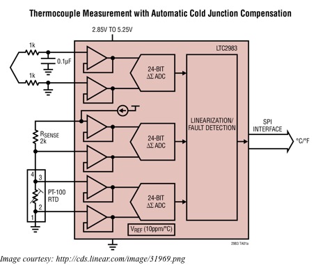
The LTC2983 carries within itself all the analog circuitry that different sensors need. It also has the necessary temperature measurement algorithms and data for linearization so that each sensor can measure temperature directly and the LTC2983 can output the results in degrees Centigrade. The IC makes it easy to handle all the challenges unique to diodes, thermistors, RTDs and thermocouples.

For example, a thermocouple will generate a voltage when there is a temperature difference between its tip and its cold junction – the tip touches the surface whose temperature is to be measured, while the cold junction is on the circuit board. Now, for an accurate measurement of the thermocouple temperature, you also require an accurate measurement of the temperature of the cold junction. A separate non-thermocouple temperature sensor, placed at the cold junction, usually does that.

With the LTC2983, you can connect diodes, RTDs or thermistors to measure the cold junction temperature. To convert the voltage output from the thermocouple into temperature, one has to solve a 14th order polynomial equation for both the voltage from the tip as well as from the cold junction. The advantage with the LTC2983 is that it has the required polynomials built into it for all the eight standard types of thermocouples – J, K, N, T, R, S and B – used in the industry. Therefore, not only does the LTC2983 measure the thermocouple output and the cold junction temperature, it also performs all the required calculations for reporting the thermocouple temperature in degrees Centigrade.

Thermocouples usually generate less than 100mV at full-scale output. Voltages at such low levels require the Analog to Digital Converter to have very low offset and noise. Furthermore, the reference voltage needed for the absolute voltage reading requires good accuracy and low drift. The 24-bit ADC within the LTC2983 has all these qualities – its noise and offset is below 1µV, and its reference voltage has a maximum drift of 10ppm/°C.

If the tip of the thermocouple is exposed to temperatures below that of the cold junction, the voltage output goes below the ground level. This complicates matters, as the circuitry requires an additional negative supply or circuitry that can shift the input level. The LTC2983 handles all this with a single ground-referenced supply, as it incorporates a front-end that can digitize signals below ground. In addition, the LTC2983 has high input impedance, low input currents and is able to accommodate external protection resistors and filtering capacitors.