Category Archives: Guides

Efficient Control of Motors at Low Speeds

When a motor is operating at high electrical frequency or high mechanical speed, the back EMF signal generated by the rotating rotor presents an efficient feedback technique for a sensor less motor control.

However, generation of the back EMF requires a minimum frequency and that makes it difficult to control motors running at low speeds. The process of continuously estimating the rotor flux angle at zero and very low speeds, together with stably moving between low-speed and high-speed estimators helps to improve the effectiveness of starting the motor under load without using sensors.

TI or Texas Instruments’ InstaSPIN-FOC software called FAST helps to make this estimation at very low speeds, sometimes below 1Hz. Although the initial rotor flux angle is unknown, FAST estimates this using sensor less techniques. Until it has measured enough back EMF, this estimate remains unpredictable and the estimated angle is incorrect.

However, FAST feeds the control system applicable to the motor and induces motor movement. Enough back EMF is generated with only a small amount of rotor movement and the algorithm can then converge on a reasonable estimate for the angle very quickly. This allows a controlled high-torque drive at low-speeds with excellent operation. Although the start-up performance may not be consistent, this method can start the motor with enough torque for rotor movement.

With increase in the starting load, the torque requirement goes up. The amount of torque the system can generate depends on the current through the motor and the alignment angle between the magnetic fields of the stator and the rotor. For ensuring generation of enough current, the speed controller must necessarily have a maximum output larger than the rated current required to generate the necessary torque.

For example, a motor starting under full load may require 4A of current to produce the necessary torque to move. This requires setting the speed controller’s maximum current output to 6A. When started, the motor will draw a current of 6A in its first electrical cycle for moving the rotor. With FAST providing a valid angle within this first cycle, the control system will quickly regulate the current usage to the required level of 4A.

However, even when there is a stable feedback angle, the rotor may not necessarily align itself properly for generating the maximum torque. In reality, you are simply sweeping the stator field and waiting until the rotor field locks on and synchronizes. If the stator field is not oriented properly, the motor may fail to generate enough torque or even produce torque in the opposite direction. Control systems can improve this situation only by starting with a better starting angle.

The simplest way to control the initial alignment is to inject a DC current in a field-oriented control system. This defines the orientation of the rotor flux. A large enough DC current injected will move the rotor and the load to a known angle. Even though the forced angle is still emulated, the orientation will be proper for correct starting and the rotor will be in the best position for produce torque. The DC current injection may be done manually or programmed through FAST.

What is a Raspberry Pi?

Raspberry Pi or RBPi, the fully functioning, tiny, single board computer costing next to nothing, has been a runaway success. However, a perennial question doing the rounds is – why would anyone want one when there is such a glut of PCs, tablets and smartphones? This article discusses the answer while exploring the RBPi doing real things.

Why is the RBPi Special?
Being an ARM-based single board computer, the RBPi, though unexceptional, is not particularly powerful. However, it is amazingly cheap and that makes it an almost disposable computer.

Several low-cost embedded systems platforms such as the Arduino are available on the market. However, unlike others, the RBPi is a complete general-purpose computer. For a very low cost, the RBPi offers the complete package of a Linux-based machine that challenges the computing power of a desktop machine of a few years ago. Apart from using it as a desktop personal machine, you can also use the RBPi as a server, a dedicated device running in kiosk mode, or for physical computing – its digital IO pins control other hardware.

The RBPi is cheap enough for one to use it to do a single job. To be equally multipurpose, other platforms would need machines that are more expensive. For example, a single RBPi can work equally well as a wall clock, a weather station, a digital photo frame, etc. Earlier, one would be using multiple temperature sensors and running long cables to a single data-collecting machine. The same job can now be handled more efficiently with an RBPi in each location, individually enabled with Wi-Fi and sending their data to another RBPi acting as a central server.

Therefore, the low cost of the RBPi is changing the optimal architecture of several projects.

Types of RBPi Available

At present, all RBPi models are based on the Broadcom BCM2835 system on a chip. This is actually a combination of a version 6 ARM architecture CPU and a VideoCore IV GPU. That makes it roughly as powerful as a 300MHz Pentium II processor typically used in the year 1999. The actual distinction between the different models is primarily based on the amount of RAM and the interfaces offered. All modes come with an HDMI and an audio port.

The initial Model A started with 256MB, while the later Models B and B+ have 512MB each. However, Linux and most applications for Linux are not as memory hungry as Windows, so the RBPi & Linux constitutes an efficient and economical combination.

Although RBPi operates on a capable Linux operating system, there are no hard disk drives and no disk interfaces either. Instead, the RBPi relies on an SD card interface that supplies the 8-32GB Operating System and file system storage.

While the Model A started with a single USB port interface, the Model B comes with a 100MHz network port and two USB ports. The latest Model B+ has one 100MHz network port and four USB ports. Therefore, you can connect a mouse and a keyboard to the Model B+ and still have two more USB ports left for connecting other appliances.

Focus Stacking with the Raspberry Pi

If you are into photography, a flatbed scanner and the popular single board computer, the Raspberry Pi or RBPi, can help you to focus stacking images in macro photography. After re-purposing an old flatbed scanner, David Hunt is using it as a macro-rail controlled by the SBC, RBPi.

Those who shoot macro photography are aware of the common issue of depth of focus limitation that shows up as the depth of field limitation in the photograph. Depending on the magnification you are trying to achieve and the camera settings, the depth of focus can be as small as 0.5mm. One solution is to stack together several images of a subject, with each image focusing on a different part of the object.

To do this with commercial solutions may set you back by as much as $600. The difficulty lies in moving the camera closer to the subject in extremely small increments, but with great accuracy. The sharp parts of the images are combined together using free software such as CombineZM, resulting in a completely sharp image of the subject right from front to back.

David Hunt decided to solve the problem with an old flatbed scanner that was lying in his attic gathering dust. Capable of 2400 dpi, the scanner had not been used for over a couple of years.

Even the drivers available for it worked only on Windows XP. Although accurate enough, David was doubtful if the machine would be capable of moving a 3Kg camera and lens combination. He decided to use the stepper motor and drive the scan element in very small increments, with the camera attached to it – it would be ideal for macro photography.

Scanners typically come with a nice flat platform on which a camera can be placed. Driving the platform forward and back requires a stepper motor that has its own drive electronics and has to be driven externally. The drive is slow, so it will let the camera remain steady while it moves. A camera with a shutter release mechanism will be useful, as you will have to take a number of snaps.

H-bridge stepper motor drives are efficient and easy to use. David used a drive capable of handling 2 DC motors or 1 stepper motor with two coils. For powering the motors and the drive, David used 3x AA type batteries. Therefore, he was able to connect four GPIO pins from the RBPi to control the drive and the motor. However, driving the motor through opto-couplers would have provided more safety for the RBPi.

The binary sequence of 1000, 0100, 0010 and 0001, when repeated, will drive the motor forward one-step at a time. The same sequence, repeated in reverse, will allow the motor to move back one-step at a time. David programmed the RBPi to generate these sequences repeatedly while he added an additional circuit for releasing the camera shutter between each movement of the platform.

With the above contraption, David can move his camera forward towards the subject in the smallest increments of 0.02mm, and take images at each increment.

Different Types of Interface Pressure Measurement Techniques

Precise measurement of interface pressure and force between two surfaces is always a challenge to engineers. However, several specific technologies exist for sensors dealing with interface force and pressure. Parameters such as form factor, precision and environment influence the selection and capabilities of such sensors.

A variety of applications requires measurement of pressure. These range from product development to medical research. Typically, pressure is the measurement of applied force over an area. With two objects held in contact, both exert force on the other. Therefore, the average interface pressure is the total force divided over the interface area. However, this interface pressure may not be distributed uniformly, creating the necessity of measuring localized interface pressure.

For measuring the force or interface pressure, chiefly three technologies are considered suitable – load cells, pressure indicating films and tactile pressure mapping systems. Although each sensing technology has some overlapping information, they all provide unique values when solving problems. Additionally, as the shape of the target becomes increasingly uneven, the ability of the sensor to match the overlap with the surfaces applying the force also becomes critical.

Load Cell

A load cell is the most common force or pressure sensor with which most engineers are familiar. The load cell has many varieties, the most useful being strain gages, piezo-electric elements and variable capacitance. Load cells may be utilized in multiple form factors depending on the force applied and the mechanics of the application. For example, measuring the deformation of a beam for qualifying the force of the load applied relies on load cells. Such compression, S- or Z-beam and shear beam load cells are all dependent on strain gages. Most reliable load cells utilize a full bridge of strain gages bonded on to the load-bearing structures.Force applied to the load cell deforms the structure and places a mechanical stress on the strain gages. This changes the resistance of the strain gages affecting their output signal. With calibration, the output voltage can correlate to the force applied on the load.

Pressure Indicating Film

These are useful when measuring interface pressure between two surfaces. A layer of polyester hides a color developing material layered next to tiny microcapsules containing staining ink. These microcapsules are designed to break under different pressures. With pressure applied to the film, the microcapsules rupture. This distributes the ink at the places where the pressure is applied. With more force being applied to a location, more microcapsules rupture increasing the intensity of color on the film. This gives an image of the force applied across the sensing area. Films are available for different sensitivities of pressure.

Tactile Pressure Sensor

Tactile pressure sensors are made of piezo-electric material. Two pieces of flexible polyester with printed silver conductors on each piece sandwich a unique piezo-resistive ink. The result is an extremely thin sensor, about a tenth of a millimeter thick. A signal is transmitted via the silver electrodes through the piezo-resistive ink. As pressure increases on the sensing area, the resistance of the ink changes and the data collected maps the pressure applied.

Different Types of Feedback Encoders

All closed loop systems use feedback to control speed and or position. This plays an important role in keeping equipment operating accurately and smoothly. When using feedback for the best benefits in an application, it is important to understand how feedback works, because a variety of devices as well as models is available for the purpose. The most popular among them are tachometers, Hall sensors, encoders and resolvers.

Tachometers
Tachometers are rotating electromagnetic devices. Typically, these are connected to the shaft of a motor, rotating when the shaft rotates and generating a voltage as a signal. The faster a tachometer shaft rotates, the larger is the magnitude of the voltage output. Therefore, the output signal is directly proportional to the speed of the motor shaft. The polarity of the output voltage indicates the direction of rotation, clockwise or counter clockwise.

Usually, analog or DC tachometers provide direction and speed information. When fed to a meter, this information can be used in servo control for stabilization. DC tachometers are the simplest of feedback encoders.

Hall Sensors
Hall sensors are solid-state electronic devices and they can sense or detect magnetic fields. The output of the sensor changes or flips whenever a magnet comes close to a Hall sensor. Therefore, a Hall sensor provides a digital output as either a high or a low voltage.

Hall sensors are used for brushless motor applications, providing information about rotor position. This works as an electronic commutation, with the controller using the information to turn on or off specific power devices applying power to the stator windings.

Encoders
Encoders are simple mechanical-to-electrical conversion devices and turn mechanical rotary motion into velocity or position information for systems controlling motion. Encoders can be rotary, digital, optical or incremental types.

In its most basic form, and encoder consists of a light source, a mask, a coded disk and a photo sensor along with related electronics. After passing through the mask and the coded disk, light from the source is detected by the sensor. As the encoder shaft rotates, light is alternately passed through or blocked, making an alternating light and dark pattern.

The associated electronics converts this into an electrical signal representing high or low corresponding to light passing through or being blocked. The resolution desired for the application governs the number of lines etched on the coded disk. By counting the number of pulses, the position of the shaft relative to its starting position is known.

There are two types of encoders, classified as incremental and absolute. Absolute encoders generate a specific address for each shaft position throughout the 360-degree rotation of the shaft.

What are Counterfeit SD Cards?

Many of us use SD or Secure Digital memory cards, but seldom do we check if the total capacity actually matches that specified on the card. According to the Counterfeit Report, several dishonest sellers on Alibaba, Amazon, eBay and other reputed sites offer deep discounts for high capacity cards. They use common serial numbers with cards and packaging nearly identical to the authentic products from all major SD card brands.

According to tests conducted by the Counterfeit Report, although the cards work, buyers usually purchase a card based on the specifications printed on it. What they think and buy as a 32GB SD card, may turn out to be a counterfeit with a capacity of only 7GB. Counterfeiters usually overwrite the real memory capacity, imprinting a false capacity figure to match any model and capacity they prefer. Usually, the actual memory capacity cannot be determined by simply plugging the card into a computer, phone or camera. Only when the phony card reaches its limit, it starts to overwrite files, leading to lost data.

According the Craig Crosby, publisher of the Counterfeit Report, such fake cards also come in capacities that do not exist in any product line and counterfeiters target mostly cards above 32GB. They make a great profit on selling fake cards, with practically no consequence.

Usually, people cannot make out counterfeit cards from real ones, until these stop working. Usually, the blame falls on the manufacturer for making faulty products. This may happen even if you buy from a major retailer, as counterfeiters buy genuine items, only to exchange them unopened with their fakes.

Although software packages are available to test whether the card capacity matches the specifications on its packaging, organizations find it time-consuming, especially if they have bought cards in bulk. Additionally, the problem is not with SD cards alone, counterfeiters make fake portable flash drives including USB sticks as well.

Although the SD Association does make standards and specifications for SD cards to promote their adoption, advancement and use, they do not monitor the trade of products such as SD memory cards. The responsibility of counterfeit SD cards falls in the realm of law enforcement.

Manufacturers of SD memory card products can contract with several SD standards-related organizations for different intellectual property related to SD standards. Additionally, SDA member companies can resort to compliance and testing tools for confirming their products meet the standards and specifications, providing assurance to users about interoperability with other products of similar nature.

Consumers, especially bulk purchasers, should be careful to buy from authorized resellers, distributors and sellers. The best resource for any enquiry is the manufacturer of the SD memory card product.

This malaise is not restricted to counterfeit SD cards alone. It is a part of a larger problem. According to the Counterfeit Report, several other items face the same situation. Phony items exist for iPhones, other smartphones, airbags and many other peripherals such as chargers. It is very difficult for consumers to make out the counterfeits and many are even unaware of the existence of such phony high-end items.

Using Mechanical Resonance to Improve Machine Performance

Traditionally, most machines typically consist of sets of gears, line shafts and oil baths. Apart from the associated maintenance required to keep the machine in top condition, product changeover can mean physically replacing a gear set or some mechanical cams. Additionally, auxiliary hardware such as compensators may be required to set the motion to its desired pace.

Now, machines driven by distributed servo drives and motors are replacing such traditional machines. The new machines provide several key benefits over their older counterparts. Since each axis in now driven by its own servomotor, there is no necessity for gear sets, oil baths and line shafts. Changing products is much easier and faster, with the motor drives changing the machine speed and switches selecting the required cam profiles. Process control is simpler since servos require only a velocity command to change tension.

However, new technology has its own requirements for achieving optimal performance. Unlike the gear train driven machines, servomotors usually require to be tuned so that they can overcome machine resonance and provide optimum performance. The usual practice follows some key steps.

The first step is to understand the fundamentals. That means analyzing the very nature of the mechanical resonances and finding their natural frequencies. This includes finding out how these resonances arise and how they interact with the several control loops.

Engineers typically use white noise for identifying the resonant frequency as the starting point. This is the primary condition that must be controlled initially through tuning the servo drives. Padding and filtering is often used as primary methods to reduce the impact of the resonant frequency on the control loop.

By adjusting the gains of each of the position control loop, the velocity loop and the current loop, engineers tune each loop such that the actual motion of the machine closely matches the desired motion.

In theory, it is possible to calculate the ideal gain of the control loop based on the inertia and stiffness of the load characteristics and the desired response. However, there can be some factors limiting the value of these gains and the desired bandwidth may not be achieved. For example, a low sampling frequency for the control loop may never allow it to settle on a stable value. However, mechanical resonance plays a more challenging role.

When a mechanical system is excited to its natural frequency, the result is mechanical resonance. The natural frequency causes ringing or vibrations with the minimum stimulus and forms an inherent characteristic of the mechanical system. The effect of resonance is noticeable at certain speeds that are usually related to the natural frequency.

When problems arise due to resonance, the typical response is to change the machine structure to move the natural frequency out of range of the machine operation. The latest converter drives are more effective in overcoming the effects of resonance without investing in additional resources.

Using Fast Fourier Transforms or FFTs, the noise spectrum is displayed as a function of frequency. This plot demonstrates the spike, which is the primary source of the disturbance. Filters are then used to remove the spike and smoothen the output.

What is Emitter-Coupled Logic?

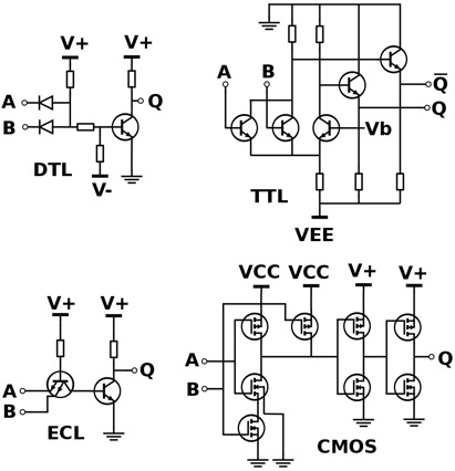
When multiple digital signals have to be combined, engineers use several types of logic gates. One of the most popular and widely used types of logic gates made of transistors is called the Emitter-Coupled Logic or ECL. It makes use of a transistor-based differential amplifier to amplify and combine digital signals. Usually, these circuits or gates, as they are commonly known, have multiple inputs and most are single output. Circuit design ensures that none of the transistors in the gate ever saturates nor are they completely turned off. That means the transistors are always working in their linear active operational region and therefore, do not have to contend with a charge storage time. That makes these gates work at extremely high speeds and this is the main advantage of Emitter-Coupled Logic gates.

For example, consider a three-input OR/NOR gate from the Motorola series of MECL devices. This circuit works on standard voltages of -5.2V (VEE) and ground (VCC). Any unused inputs have to be tied to VEE to prevent erratic behavior. The bias circuit is made up of transistors and associated diodes and resistors (not shown). The circuits are generally packaged as integrated circuits as multiple gates in a single IC. Typically, such ICs include quad 2-input, triple 3-input and dual 4-input gates. Here, the gates differ only in the number of input transistors they are built of, while a single bias circuit suffices for all the gates.

While in operation, a logic output changes its state from a high of -0.75V to a low of -1.60V, a change of only 0.85V. The differential amplifier transistors receive a fixed bias of -1.175V from the internal bias circuit. Now, if all inputs are at -1.6V or tied to the VEE rail, the input transistors are turned off, with the internal differential transistors alone conducting current. This causes the base voltage of the OR output transistor to reduce and its output voltage remains at -1.6V. Simultaneously, since none of the input transistors is affecting the base of the NOR transistor, its output rises to -0.75V, which is the emitter-base voltage VBE of the transistor itself. All transistors in the IC are designed to show a VBE of 0.75V.

As soon as an input rises to -0.75V, that transistor draws emitter current away from the internal differential transistors. This causes the outputs to switch states. Although these circuits work with very small voltage changes, which are typically dictated by the VBE of the internal transistors, the current flowing through various parts of the circuit is of greater importance. This is why Emitter-Coupled Logic has another name – Current Mode Logic or CML. Many other logic types also implement the CML and all of them suffer a major drawback – they draw a great deal of current from the power supply and tend to dissipate heat to a significant amount.

To counter this drawback, other logic systems have evolved, such as TTL and CMOS. For example, high-speed devices such as frequency counters employ ECL only at the input ends of their circuitry, following it up with high-speed CMOS or TTL counters at later stages.

Different Types of Digital Logic Gates

digital logic gates explained
In the presence of different digital signals that need to be combined to make a logical decision, engineers use different types of digital logic gates. Usually, these gates have several inputs but a single digital output. Where a larger logic gate function or a sequential or combinational circuit is required, it is usual for individual logic gates to be connected together.

Digital logic gates in standard commercial form are available in two basic forms or families – TTL or Transistor-Transistor Logic and CMOS or Complementary Metal-Oxide-Silicon. An example of the TTL types is the 74xx family and the 4xxx family for the CMOS types. The notation TTL or CMOS is the logic technology that manufacturers use for the Integrated Circuit or IC or chip as commonly known.

The difference in the two families depends on the type of transistors used in making these ICs. While ICs using the TTL logic make use of PNP and NPN type of Bipolar Junction Transistors, the CMOS logic uses JFET or complementary MOSFET type of Field Effect Transistors for their input as well as output circuits.

Apart from the TTL and CMOS technologies, other simpler types of Digital Logic Gates also exist. Some involve the use of diodes, resistors and transistors strung together as RTL or Resistor-Transistor logic gates. Other types are DTL or Diode-Transistor logic and ECL or Emitter-Coupled logic. However, these are far less common compared to the popular TTL and CMOS family, owing to the lower power consumption and heat dissipation of the latter types.

It is usual for ICs to be grouped together into families based on the number of gates or transistors they contain. For example, a single OR gate may be made up of only a few individual transistors, whereas complex micro-controllers have several thousands of individual transistor gates. This leads to integrated circuits being classified as Small Scale Integration or SSI, Medium Scale Integration or MSI, Large Scale Integration or LSI, Very-Large Scale Integration or VLSI, Super-Large Scale Integration or SLSI and Ultra-Large Scale Integration or ULSI. Most complex micro-controllers, video processors, GPUs, CPUs, PICs & FPGAs are examples of ULSI containing several million transistors.

The most modern level of integration, representing the increasing complexity of modern digital circuits, is the Systems-on-Chip or SOC. Here, a single piece of silicon forms the base for individual components such as IO logic, peripherals, memory and the microprocessor. This represents a complete electronic system within the individual single chip.

The Digital Logic Gate forms the basic building block for construction of the entire field of digital electronic circuits and all microprocessor based systems. Digital Logic Gates fundamentally perform logical operations such as AND, OR and NOT on binary numbers represented by digital voltage signals.

The digital logic design recognizes only two voltage levels or states. These are generally referred to as the True, High or Logic “1” and False, Low or Logic “0” states. In Boolean algebra and in standard truth tables, the digits “1” and “0” represent the two states. In terms of voltages, digital logic systems typically use a “Positive Logic”. Here, the level “0” is represented by 0V or ground potential and a higher voltage such as 1.8V or 3.3V or 5.0V represents level “1”.

How do Piezomotors Work?

Voltage applied to a piezoelectric material causes it to change its shape very minutely. Piezomotors such as Piezo LEGS are ceramic actuators that have four legs as its motors. These are designed cleverly such that the applied voltage can either elongate the legs or bend them sideways. It is also possible to synchronize the movement of each pair of its four legs such that it begins to walk just as an animal would – step by step. While walking, the legs can also stop at any instance on a nanometer level. The driving rod produces direct friction coupling with the legs. That means piezomotors can operate without any mechanical play or backlash. The direct drive, apart from providing full force, also offers power-off locking that does not require any power consumption.

However, the friction coupling between the drive rod and the internal piezo actuator legs does not allow counting the steps or knowing the position of the legs accurately. When they are under constant load, the legs face a certain vibration between the steps. As the load or temperature varies, so do the vibrations. Therefore, separate position sensors are required to know the accurate position of the legs of a piezomotor.

Piezomotors can move extremely slowly. When running in a closed loop system, you can make them achieve a continuous smooth motion at speeds under 1µm/s or 0.001mm/s. Since the speed of a motor depends on its step length and step frequency, a typical linear piezomotor is limited to a maximum speed of 10-15mm/s. In reality, the speed depends on both the external loads and temperature. Therefore, to run the motor at constant speed, you must have a closed loop controller.

Compared to conventional motors, piezomotors are very energy efficient. For example, when in a hold position, piezomotors do not consume any power. They also do not draw peak currents while starting or stopping. Power consumption of such motors is not dependent on inertia. That means the motor will consume the same amount of power under different external torque/load. When operated with a low duty cycle and for point-to-point applications, piezomotors provide excellent battery life.

Just as in regular stepper motors, one can define holding force and stalling force for piezomotors as well. While running, the highest load that the piezomotor can hold dynamically without slipping is called its stalling force. When powered down, the motor is able to hold a load statically and the maximum load that it can statically hold without slipping back is called its holding force. In general, the holding force of a piezomotor is about ten percent higher than its stalling force.

Although the operating principle of a piezomotor is very similar to walking, it can walk with full steps, reduced steps and it can even do micro stepping. Usually, the drive rod or disc will engage with the two or more actuator legs to move them forward and release. Then it will engage with a second set of legs to move them forward. This cycle repeats as long as the motor walks. Therefore, it is always possible to divide the full step into several smaller steps – also called micro stepping.