Category Archives: Guides

Why Does My Motor Need A Capacitor?

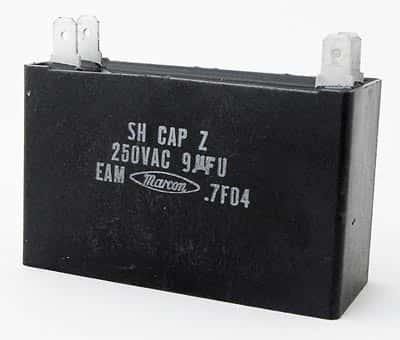
Motor CapacitorIf you are using an AC pump to raise water from a sump to an overhead tank, chances are it uses a squirrel-cage type motor, which needs a capacitor to make it work. This is true for single-phase motors, where the capacitor creates an artificial second phase necessary to generate the rotating magnetic field and make the rotor start spinning. Once the rotor starts rotating, the interaction between the stator and rotor keeps the magnetic field spinning.

A single-phase motor has a primary winding and a secondary winding. If connected to the AC supply without the capacitor, both windings produce magnetic fields of the same phase resulting in zero torque. With a capacitor connected in series to the secondary winding, the magnetic field it produces lags behind the magnetic field generated by the primary winding. This difference in phases creates a starting torque and the motor starts to rotate.

Capacitors that allow a motor to start rotating are called start capacitors. Smaller motors usually have the start capacitor permanently connected in series to the secondary winding. Big motors require a larger capacitor to help them generate the starting torque, but they run more efficiently with a small capacitor in place, called run capacitor. Often both capacitors are housed in the same can, which then has three terminals in place of the customary two. Such motors have a centrifugal switch to disconnect the start capacitor when the motor has reached 70-75% of its full speed. Start capacitors are typically of high value of 100 or more microfarads, while run capacitors are smaller, of about 25-47 microfarads.

You will find motors with large start capacitors being used for several applications where it is necessary to generate considerable torque to begin moving the load. Such applications include mechanical conveyors, belted blowers and commercial garage door openers. These are mostly electrolytic capacitors, housed within a plastic or metal can. Inside the can are two metal foils rolled up with a flexible paper-like insulation separating the sheets. The paper, soaked with an electrolyte, forms the dielectric of the capacitor. The two metal foils are connected to two terminals. The assembly is sealed with epoxy and the two terminals are available for external electrical connection.

Large HVAC units sometimes need two run capacitors, because they have both a fan motor and a compressor motor. To save space, manufacturers combine the two physical capacitors into a single can. Such dual capacitors have three terminals and they are usually marked as Common, Fan and Compressor.

You will find a variety of combinations for dual capacitors, for example, 40 + 5uF, 370V or 100 + 25uF, 440V and others. Their shapes can be cylindrical with a round or oval cross-section. A capacitor’s ability to hold charge is measured in microfarads. As electrolytic capacitors age, their capacity reduces. That results in the motor failing to start or run at less than full speed.

Motors are not fastidious about the capacitance value of the capacitor used for starting. However, when replacing a faulty capacitor, you must never use a replacement that has a lower voltage rating. Always use a part with a voltage rating that is the same or higher than the rating of the capacitor you are replacing. Of course, it’s always preferred to replace a capacitor with another that has the exact electrical specifications for the best results – both in performance and safety.

Using eGaN FETs in Wireless Power Transfer Systems

Highly resonant wireless power transfer systems such as the A4WP use loosely coupled coils operating at the standard 6.68 MHz or 13.56 MHz unlicensed industrial, scientific and medical ISM bands. The popularity of such wireless energy transfer is increasing over the last few years specifically for applications targeting charging of portable devices. Usually, such solutions for wireless energy transfer for portable devices demand features such as lightweight, high efficiency, low profile and robustness to varying operating conditions.

Such features call for efficient designs capable of operating without bulky heat sinks and able to handle a wide range of load variations and couplings. Only a few amplifier topologies can meet such extreme demands and these are the current mode class-D, the voltage mode class-D and class-E. Of these, class-E is the most popular choice for several types of wireless energy solutions, chosen for its ability to operate with very high conversion efficiency.

As compared to regular MOSFETs, eGAN FETs have demonstrated superior performance when using voltage mode class-D topologies in a wireless energy transfer application In fact, eGAN FETs showed higher peak efficiencies of more than four percentage points. At output power levels beyond 12 W, regular MOSFETs required the addition of a heat sink to provide the necessary cooling for the switching devices and their gate drivers.

Moreover, in the traditional class-D topology, the resonant coils needed to be operated above resonance for them to appear inductive to the amplifier. Operating the coils above resonance reduced the coil transfer efficiency resulting in high losses in matching the inductor because of its reactive energy.

Working in class-E topology, eGAN FETs were able to deliver as much as 25.6 W of power to the load while operating at 13.56 MHz. Transferring wireless energy with high load resistance of about 350 ohms made sure the system had a high Q resonance. Measuring the system efficiency gave a figure higher than 73%, which included gate power consumption.

In a single-ended class-E circuit, the series capacitance resonates with the reactive component of the load yielding only the real portion of the coil circuit to the amplifier. The design of the matching network works for a specific load impedance and establishes the necessary conditions of zero voltage and current switching.

In tests comparing the performance of MOSFETS and eGAN FETs, temperatures were kept well below 50C, when operating in an ambient temperature of 25C. No forced-air cooling or heat sinks were used during the tests, which used the same gate driver for driving both the eGAN FET and the MOSFET.

Measurements show the eGAN FET requires significantly lower gate charge for the same operating conditions and this is an important consideration for low power converters. Gate power forms a significant portion of the total power processed by the amplifier. Additionally, as the eGAN FET has a 33% higher voltage rating compared to a MOSFET, it can be operated at higher voltages for higher output power.
Therefore, the simple and efficient class-E topology, coupled with eGAN FETs, is well suited for wireless transfer converters.

How do Wi-Fi Antennas Work?

Antennas are necessary for transmitting and receiving the radio-frequency energy that forms the basis of Wi-Fi communications. The underlying rule is you need a better antenna to improve coverage. Understanding fundamentals is essential for selecting a proper antenna for your application.

In general, antennas radiate radio waves when fed with the right kind of electrical power. Conversely, an antenna can also covert radio waves received by it into electrical power. There are different forms of antennas, some created intentionally, such as those on your wireless router, and others created naturally, such as the wires on your earbuds, which act as antennas. Antennas are usually directional, meaning they are better in transmitting and receiving radio waves in some directions than in others. However, there are omnidirectional antennas that work nearly equally in all directions.

Wi-Fi antennas are mostly dipole types, or more specifically, half-wave dipoles. They consist of two halves, each equal in length to a quarter of the wavelength they are to transmit or receive. A separate conductor from the feedline feeds each half separately. For example, for a frequency of 2.45GHz, a half-wave dipole antenna would be 61.22mm from one end to the other, while each half measuring 30.61mm. However, other parameters also affect the length of the dipole and the resulting antenna may differ considerably from theoretical calculations.

Examining a Wi-Fi antenna from a 2.4GHz wireless router reveals a hinged base connected to a plastic cover. The hinge allows antenna rotations irrespective of the mounting position of the router. Within the plastic cover, you can see the entire dipole antenna. One-half of the dipole is made of a metal cylinder through which the feeder wire passes. The other half is the wire itself that protrudes to the other side of the cylinder. With the metal cylinder and the wire insulated from each other, they form a dipole of approximately one-quarter wavelength long. Such antennas have a gain of about 2dBi and their radiation pattern is circular.

The antenna connects to the Wi-Fi radio transceiver via a wire feedline – a coaxial cable. This has an insulated inner copper conductor covered with an outer braided shield made of copper wires. A clear plastic cover encases the entire feedline. Wi-Fi devices use these feedlines, also known as coax and designated RG-178, specifically for their small size and relatively low RF losses.

Antennas are usually better in transmitting and receiving radio waves in certain directions. Their ERP or Effective Radiated Power is greater in those directions. Although the total radiated power remains the same, antenna gain refers to the increase in strength in several directions than in others. Therefore, simple horizontal dipoles show gain in two directions – parallel to the radiators on both the front and backsides.

Depending on the country that is using the Wi-Fi signals, there are five different bands of transmission – 2.4GHz, 3.6GHz, 4.9GHz, 5GHz and 5.9GHz, with correspondingly matched antenna lengths. Although the general principles apply to all bands, the most widely used transmission for Wi-Fi signals is the 2.4GHz band. Usually, this extends from 2.4GHz to 2.5GHz.

Track Mobile Assets with this 4G LTE Router

Organizations with fleets of vehicles to manage do not find it an easy task. It is important for them to focus on the bottom line without sacrificing service, response time and customer experience. Tracking mobile assets is a complex issue for fleet management that organizations in numerous verticals have to grapple with every day.

Saving operating costs can help pay for an investment in fleet management solutions. A good solution provides savings with optimized vehicle utilization, operator compliance and lowers training costs, besides saving fuel and maintenance costs through Information – the key to reducing costs. Typically, a fleet manager has to know whether drivers are operating safely, choosing efficient routes while staying within authorized boundaries; whether any vehicle is being used for unauthorized purposes, is under-utilized or idling needlessly; whether a vehicle will need preventive maintenance to avoid expensive repairs; location of the vehicle closest to an urgent call that just came in; when an older vehicle should be cycled out; which vehicles do not use fuel economically, etc.

You can monitor all this and more with the 4G LTE router and associated tools from CalAmp. Their flagship router, the LMU-5000LTE has support for a broad range of wireless connection options. It comes equipped with interfaces for all types of vehicles, including light and heavy-duty vehicles and it can monitor the vehicle status, location and behavior of the driver. With the Programmable Event Generator, PEG, which is the industry-leading on-board alert engine, the fleet manager has access to real-time information. With this, he can define rules that enable the application to take action as values exceed a threshold that he has specified.

Running embedded Linux on a 400MHz ARM9 processor, the LMU-5000LTE features fleet tracking and the user-programmable PEG monitoring software. It is equipped with multiple IO, a 5-channel GPS, EVDO, HSPA, and LTE routers. LMU-5000LTE is a cellular router and gateway for AT&T networks.

If you are looking for greater flexibility in designing your solution, CalAmp has the LMU-4230. This includes an even greater set of fleet features using cellular, Wi-Fi, Bluetooth and option for satellite connectivity. A three-axis accelerometer assesses Vehicular performance such as impacts, aggressive acceleration or hard braking. An optional interface, the JPOD ECU or Engine Control Unit allows reading and transmitting heavy-duty engine conditions and performance data. This includes engine temperature and fault codes to provide the optimum real-time picture of the health of your vehicle.

With the LMU-5000LTE, organizations can set up managed cellular networks via AT&T’s mobile broadband network working on 4G LTE. The device combines gateway, routing and M2M monitoring functions. According to CalAmp, the unit supports remote monitoring and control, enterprise fleet management, industrial and energy remote asset management, point-of-sale applications and workforce automation.

The Linux-based firmware on the device and CalAmp’s PEG alert engine monitors external conditions and responds to exception-based rules defined by the user. The user gets a feedback on violation of any threshold such as time, date, motion, location, geo-zone and inputs. CalAmp also provides PULS or Programming, Update and Logistics System for management and maintenance for over-the-air devices.

How do Sensors Measure Gear Tooth Speed and Direction?

Measuring speed of gears is an important factor in various industries, especially in pharmaceutical, tobacco, printing, woodworking, paper, textile, food and others where rotational machinery predominates. Gear speed measurements also necessary in pumps, blowers, mixers, exhaust and ventilation fans, wheel-slip measurement on autos and locomotives, flow measurement on turbine meters and many more.

The most common gear tooth sensors detect a change in the magnetic field for determining the speed and direction. Usually, these are of three types – the Hall Effect, magneto-resistive and the Variable Reluctance. There are optical types of sensors as well, detecting a change in light levels as the gear rotates past the sensor.

Sensors using magnetic properties are good for measuring speed and direction of gears made of ferrous metals. All these sensors are non-contact type and sensitive to detect the presence of gear teeth passing in front of the sensor. As a gear tooth comes close to the magnetic sensor, its output flips and the electrical level at its output changes state. The output remains steady as long as the gear tooth is within the detectors sensing zone. As the tooth passes out of this zone, the output flips back. Therefore, a magnetic sensor placed in front of a rotating gear, the output from the sensor will be a series of electrical pulses.

There are several advantages when using magnetic sensors. Apart from the sensors being non-contact type, they are robust, hermetically sealed and can withstand unregulated power supply. Most manufacturers make then RoHS and IP67 compliant. That means no lead or other toxic materials are used for manufacturing these sensors and dust or liquid will not enter their enclosure. That makes such sensors suitable for use in food processing industries.

For measuring the speed of gears made of non-magnetic material, engineers often use optical sensors. The most common sensor of this type is the optical interrupters. Gear teeth interrupt a light beam from an LED source and the detector produces a corresponding electrical output. A continuously rotating gear in front of the sensor therefore, creates a similar series of electrical pulses as the output from magnetic sensors do.

The functioning of optical speed or proximity sensors is dependent of the dust and dirt level of the environment where they are used. Therefore, their range of applications is somewhat restricted as compared to magnetic sensors.

Measurement of direction involves a reference point, which means two sensors need to be used, with one of them being the reference sensor. An electronic circuit measures the time gap between the responses from each sensor. As the gear tooth passes in front of both sensors, one of them will change output before the other. If sensor A happens to trigger before sensor B does, the electronic circuit determines the gear is moving from A towards B. In case the output of sensor B switches before sensor A does, then the gear is moving from B towards A.

Usually, the sensors provide separate digital outputs for speed and direction. Their measuring capability may extend from detecting near zero speed up y 15 kHz.

How do Sensors Measure Angle?

An angle is the degree of rotation of an object from a reference position about a central axis. In the engineering world, there are two types of angles requiring measurement. One is the physical or mechanical characteristic, such as the rotation of a shaft with respect to its bearing or housing. The other is a mathematical term such as the angle between two phases of alternating voltage system. Usually, sensors measure angles in a format that a computer or a machine can understand, interpret and utilize.

It is also a common practice to convert a physical characteristic into a rotational mechanical movement to measure linear displacement. For example, the distance traveled by a shaft can be translated into rotational movement by a rack and pinion arrangement. The angular position sensor attached to the arrangement then interprets the angular movement in proportion to the linear movement of the shaft.

In the market, you will find different sizes and forms of angle positioning sensors using various technologies. Generally speaking, these sensors are versatile and one can use them in all kinds of applications, such as in agriculture, commercial equipment, off-road vehicles and in automotive industries. Most of the applications above require a product suitable for operating in harsh environments, including moisture, dirt, dust, extreme temperatures and more.

For example, Forklift Position sensors measure the angle of the forks on a forklift truck. According to OSHA, one of the primary causes for tip-over accidents on forklifts is excessive speed when the machine is turning or rounding a corner. The angle position sensor on the truck helps it to remain within a safe speed and prevents overturning. This particular application also prevents accidents from unbalanced loads and limits the operation of the machine when the load is improperly positioned or balanced.

The simplest form of measuring angle is by using the gear tooth sensor. By sensing the teeth to count the rotation of a gear or wheel, engineers monitor and limit speed. Another common form of angular position measurement utilizes potentiometers. Other more sensitive and rugged types of angle sensors use optical or magnetic technology.

Traditional rotary encoders use an LED transmitter, a coded disc and a photo sensor to detect angular movement. The disc is coded with opaque and transparent sections, which transmit light in a specific manner to the photo sensors depending on the position of the disc. The photo sensor converts the light falling on to it into an electrical code. This allows the encoder to detect rotation, position, angle, etc.

Sensors that are more rugged use the Hall-Effect technology for measuring angle. This technology uses magnetic field sensing and does not require the critical positioning necessary for the components using optical methods. In both methods, accuracy of an angle sensor depends largely on its resolution. The higher the resolution, the more precise is the detection of angular movement. Sensors measuring angles using Hall-Effect technology can perform without physical contact, thereby remaining unaffected by vibration and abrupt movements. These sensors also have the added benefits of virtually unlimited lifespan.

The Ultimate GPS HAT for the Raspberry Pi

If your smartphone is lost or misplaced, you can trace it using its GPS or Global Positioning System receiver. The US Department of Defense has placed 24 satellites into the Earth’s orbit making it a satellite based navigation system. Although GPS was conceived originally for military applications, in the 1980s, the government allowed the civilians to use the system as well. GPS works without any subscription fees or setup charges for 24 hours a day, covering the entire world in any weather condition.

Circling the earth twice a day in very precise orbits, the GPS satellites transmit signal information to the earth. GPS receivers calculate their exact location by receiving and tri-lateraling this signal information. GPS receivers compare the time the signal was transmitted from the satellite with the time of its reception. The difference tells the GPS receiver its distance from the satellite.

After computing the distance measurements from at least two more satellites, the receiver determines its 2-D position and displays it on the electronic map of the unit. That allows it to know its latitude and longitude and to track its movement. If the receiver is able to contact four or more satellites, it can determine its 3-D position – latitude, longitude and altitude. With this information, the GPS unit of the receiver can compute other information such as speed, track, bearing, trip distance, sunrise and sunset time, distance to destination and much more.

The popular single board computer, the RBPi or Raspberry Pi, does not have a GPS receiver built-in. However, you can add a GPS unit to the SBC by plugging in a new HAT from Adafruit. This Hardware Attached on Top board conforms to standard specifications, enabling the board to be identified by the RBPi. Once identified, the SBC configures its GPIO ports and its drivers to suit the attached HAT.

The new HAT has an Ultimate GPS on it and enables the RBPi to know its exact position and time. It fits the RBPi Models A+ or B+. If you slip in a coin cell in the holder provided, it will power its RTC, and the RBPi will keep precise time. As the GPS unit does not take up much space, the HAT has plenty of prototyping area for adding sensors, LEDs and much more.

It must be noted that the GPS HAT uses the hardware UART of the RBPi. Once you are using this HAT, you will be unable to use the Rx/Tx pins of the RBPi for any other purpose. If you plan to use the GPS HAT along with a console, you will have to change the application and use a composite or HDMI monitor and log in with a keyboard. Of course, you can still use ssh to connect to your RBPi over the network.

Adafruit has very informative tutorials for using this HAT. They offer the HAT in a fully assembled condition, with the GPS unit already soldered in along with an unsoldered 2×20 header for sitting on the RBPi GPIO. Once you have soldered in the header, you are all set to connect the GPS HAT on your RBPi. The coin battery is not included in the kit.

The Raspberry Pi Piano HAT

Not only musicians, but children also like to play on pianos. A real piano takes up too much space and is an expensive acquisition, but electronic pianos are affordable and their small size offers a great opportunity for music aficionados to practice at their leisure. Creating a piano with a Raspberry Pi or RBPi, the versatile single board computer, enables the designer to learn to program a computer as well as distinguish nuances in music.

That inspired the 14-year old Zachary Igielman to design PiPiano, and the Piano HAT is based on Zachary’s PiPiano. Where PiPiano is an add-on for the RBPI, the Piano HAT is a full-fledged Hardware Attached on Top board specifically designed for the RBPi.

Hardware Attached on Top or HAT boards sit on the RBPi models B+, conforming to a specific set of rules. HAT boards include a system to allow the RBPi to identify it. Based on the identification, the RBPi automatically configures its GPIO pins and drivers to suit the HAT board.

You can use the Piano HAT with RBPi models 2, B+ and A+. The kit comes in a fully assembled state and has a trove of software examples so that you can start playing music with it immediately as soon as you plug it in. The Piano HAT is completely touch-sensitive and you can use it to play music and generate software synthesizers using Python, control hardware synthesizers or simply be creative.

The Piano HAT kit comes with 16 touch-sensitive buttons, a full octave of 13 piano touch keys, buttons to shift the octave up or down, an instrument cycle button and 16 LEDs. You can let the program play and light up the LEDs auto-magically, or control them with Python.

You can use Python to program the 16 touch-sensitive buttons individually on the Piano HAT. Hook up the buttons to any of your projects and use them as you like. Two dedicated buttons are available to allow you to shift the music scale up or down an octave, offering a chance of expanding your playing horizons.

Using a little Python glue, it is possible to send a patch change event from your RBPi to a synthesizer such as the Yoshimi – the Instrument cycle button allows this. With the 16 LEDs available, you can light up the keys, making the Piano HAT a learn-to-play keyboard. With Python, you can use the LEDs as a visual metronome or allow your child to walk through his or her favorite tune.

The Piano HAT and RBPi combination, with some Python programming thrown in, allows creation of Piano-controlled contraptions. This includes a variety of synthesizers, both hardware and software types. MIDI examples included in the kit let you play music with synthesizers such as the Yoshini, Sunvox and others. The kit also includes a PyGame example that can generate a few octaves of great piano and includes drums as well.

Python on your RBPi allows your Piano HAT to output regular MIDI commands, with which you can use your MIDI adapter over USB to take control of your hardware synthesizer gear.

How do you select a Tactile Switch?

We find tactile switches almost everywhere – on keyboards, on mice, beside the monitor, on TV sets, on set-top boxes, on toys and on mobile phones. These tiny switches give a distinctive feeling when pressed. We are so used to using tactile switches; we press them a dozen times a day and never think twice about them – that is, as long as they work. However, tactile switches can also stop working, and engineers must select tactile switches with great care so they last long. After all, most feel that a bad or nonfunctioning switch equals a bad device.

Therefore, to avoid the possibility of a quality black eye, you must essentially select the right switch. Deciding what it is that exactly makes a tactile switch right of the job, may depend on a host of factors, of which two are most important. One is the actuation force and deflection characteristics necessary to meet the requirements of the application. The other is the reliability with which the switch must work during the life of the host electronic gadget.

Thinking of switches as commodity items selected straight off a datasheet, is an expensive mistake that many engineers do make. In reality, picking a durable switch with the right feel does require somewhat more than a mere glance at its specifications. Here is what you should be looking for.

Click ratio

The click ratio of a switch expresses the relationship of its actuation and contact forces. A higher click ratio is indicative of a snappier or crisper switch feel. The deflection or travel distance of a pressed switch also contributes to its overall feel.

A typical datasheet holds the force and travel specifications and these can be a starting point for selecting a switch that feels just right in its intended application. However, the ideal switch depends on the application – an important thing to remember.

For example, users of portable consumer electronic devices prefer crisp tactile switches that have a relatively high click ratio and shorter travel distances. On the other hand, tactile switches for the automotive industry need lower click ratios and longer travel distances. This prevents accidental actuation while driving. Therefore, each electronic application needs to reach a unique balance between the travel distance and the actuation forces.

Sealing

Consumer electronics and medical applications need tactile switches that are protected against ingress of liquids and other contaminants – IP 67. Usually, these sealed tactile switches reach their maximum lifecycle, because of the sealing.

Manufacturers have traditionally used a bonded silicone membrane to seal the innards of a tactile switch. Now, technologically improved IP67 rated tactile switches use a patented laser welding process that seals the switch with a thin nylon film. This goes over the actuator rather than under it, giving a better seal. The seal not only preserves the crisp feel, but also protects the switch against side loads.

Reliability

Protecting the switch with the nylon film improves its inherent reliability by not allowing ingress of contaminants. The best switches will typically offer a life expectancy of above one million press-and-release cycles.

How do AC Current Sensors Work?

You can sense current using a series resistor and measuring the voltage drop across it. According to Ohm’s law, the current through the resistor is then the voltage drop divided by the resistance value. That makes the voltage drop proportional to the value of the resistance and the current flowing through it. The disadvantage is obvious – to prevent the voltage drop from affecting the circuit parameters, one needs a very low value resistor when the current involved is high. Additionally, as the current reduces, so does the voltage drop. That involves amplification of the voltage drop, creating additional circuit complexity.

Ideally, current sensors should not use any power when detecting the current in the circuit. However, real current sensors do require a part of the energy from the circuit for providing the information. For sensing AC currents, current sense transformers are typically useful. A single wire from the circuit acts as the primary of the transformer or the primary may be a single turn winding on the transformer.

The AC current sense transformer develops a current in the secondary, proportional to the sensed primary current. The secondary current is allowed to flow through the terminating resistor to produce an output voltage. As the turns ratio of the transformer decides the secondary current, a low turns ratio (pri/sec << 1) minimizes the current through the terminating resistor. A balance of the transformer ratio and low-enough current through the terminating resistor ensures adequate output voltage. You select the appropriate AC current sensor based on the frequency range and current rating of the sensor for the conditions of your application. The highest flux density to prevent saturation of the sensor core will then depend on the worst-case current and frequency conditions in the circuit. The requirement is to generate a voltage output from the sensor that will vary linearly with the current being sensed. If the core saturates, the output becomes non-linear, and the output voltage is no longer strictly a representative of the input current. Sensors come in surface mount or through hole types, with different turns ration and overall dimensions. As noted earlier, you can have a sensor only type, which has a conductor integral to the application serving as the primary. The other is a current transformer type, where the primary is an included winding. Current transformer manufacturers offer online selection tools for selecting the right current sensor for the specific application. Initially, the user selects either an SMT sensor or a leaded type of sensor. The tool then requires the user to input the maximum sensed current expected, the input frequency, the duty cycle of the primary current waveform and the desired output voltage. The output voltage being the desired output voltage for the maximum input current the user expects. Based on the maximum input current, the number of secondary turns and the output voltage necessary, the tool suggests the required terminating resistor value. For this calculation, the tool assumes a single-turn primary. The tool also provides the maximum flux density based on the above parameters and the maximum operating frequency, making sure the value does not exceed 2K Gauss to ensure linearity.