Category Archives: Guides

Pi-Top: Convert your Raspberry Pi into a Laptop

Although we call the Raspberry Pi or RBPi as a single board computer and it is small enough to fit in your pocket, it is hardly useful as a computer when you are on the move. This is mainly because the SBC comes without a keyboard, display, and mouse, intended to keep the costs down. However, if you are interested in turning your RBPi3 into a laptop, there is the Pi-Top.

You get everything necessary to turn your $35 single board computer into a laptop. For instance, you get a 13.3” HD LCD screen with an eDP interface and 1366×768 pixel resolution, which comes with an active 262K color matrix, anti-glare finish, and a 60 Hz refresh rate TFT LCD module. Additionally, you get a keyboard that is fully programmable via USB and a trackpad with a PalmCheck feature that helps prevent unwanted mouse clicks.

Although the Pi-Top converts the RBPI into a general-purpose laptop, its actual strength lies in its being a tinkerer’s toolkit. Pi-Top gives you great power management with LED battery indicators. The power supply requires an input capable of 18 V at 3 A, while it offers two outputs, one of 5 V, 3.5 A, and the other at 3.3 V, 500 mA. One good feature is the 3.3 V output is persistent. That means this voltage is available even when you have powered off the Pi-Top. Battery capacity is substantial, giving a run-time of 10-12 hours. There is protection for all outputs from over-current, over-voltage, over-temperature, and short-circuit. The smart battery pack uses a charging profile recommended by JEITA.

The hub-board of the Pi-Top has a screen driver that converts the HDMI output from the RBPi to the eDP 1.2 interface required by the LCD screen. It allows connection of UART, I2C, and SPI to the RBPi for use with add-on boards. There is even a PS/2 interface. The screen consumes 3 W, but you can dim it with a PWM screen dim control to make it consume less power.

Pi-Top comes with a manual to walk you through the assembly process in steps, while identifying clearly the part necessary to use at each stage. The manual has a pictorial guide to help in assembling the laptop. That makes the job relatively simpler. Since all the tools you need are already included, piecing together the case, cables, and boards into a working laptop is an unforgettable experience. However, you do need to be careful when tightening the smallish 2.5 mm nuts that hold the boards in place, as there are various electronic components on the boards.

Once assembled, the Pi-Top is an impressive sight, with its fluorescent green finish. The external case is injection-molded plastic and is sturdy enough to be travel-worthy. When powered on, you may be surprised at not seeing the familiar Linux-based Raspbian desktop on the screen. That is because the PI-Top re-skins the Raspbian desktop as the pi-topOS. Basically, they have added a launcher and configured the desktop to add a menu button at the bottom left corner – familiar to long-time Windows users with the Start menu.

Where Would You Apply Crowbar Protection?

Crowbar is an appliance typically used by construction workers. It is a heavy steel rod with one of its ends pointed and the other shaped like a spatula – both very useful for digging or breaking up construction rubble. Normally, one would not associate such a crude instrument for use by engineers dealing in electronics, were it not for one unusual property of the crowbar. Throw it across a power line, whether accidentally or with a purpose, and the power line trips – a fail-safe arrangement to protect the load in case of an emergency.

In electronics, a crowbar protection is generally an electronic circuitry placed across the outputs of a power supply. It activates to protect the load against overvoltage. When it activates, it shorts the output terminals – the crowbar action. This serves to blow the fuse, trip the circuit breaker or to shut down some part of the circuit so that power to the load is cut off. Most power supplies, whether low- or high-voltage, employ this kind of protection.

The crowbar protection circuit has a sensor that monitors the output voltage of the supply, comparing it against a preset value. When an overvoltage occurs, it triggers the crowbar circuit, which in turn short circuits the output terminals, thereby cutting off power to the load.

Crowbar devices typically use one of two types of components as their main protection. These are the Silicon Controlled Rectifier or SCR, and the Metal Oxide Semiconductor Field Effect Transistor or MOSFET. The design of the monitoring circuit of the crowbar depends on the sensitivity of the load circuit to be protected. For instance, the reaction time of the monitoring circuit depends on how long the protected circuit can survive the excess voltage without damage, and the response time of the main protection device.

Several fault-conditions may lead to possible over voltages. These include a fault in either the power supply or the load, and operator error. Present day electronics are sensitive and often operate at very low voltages with small margin. That makes it imperative to ensure that the safe voltages are not exceeded, and sensitive and expensive equipment remain undamaged.

Although blowing the fuse is a popular method of protecting a circuit, it has its disadvantages. Recovery is only possible by manually replacing the fuse, once the fault condition is repaired. This is a time consuming affair, and not helpful for low downtime appliances. Therefore, most engineers prefer a fold-back type of crowbar protection.

In a typical crowbar protection, the entire load current is diverted from the load and directed to the short circuit across the output terminals. This is constant current limiting and puts the fuse under tremendous stress, causing it to blow, thereby protecting the power supply and its load. In contrast, with the fold-back crowbar protection, the load current through the short circuit reduces once the crowbar has activated and shorted the outputs.

The short circuit current reduces to the extent that the power dissipated by the supply can remain within its safe operating area. This prevents the fuse from blowing, and at the same time, the power supply keeps the load circuit safe because of the crowbar action. As soon as the cause of the overvoltage is repaired, the power supply resumes automatically.

Driving Motors and Servos with the ZeroPi

If you are looking for a development board for the 3-D printer you are designing, ZeroPi may be the best fit. Suitable for use with the Arduino and the Raspberry Pi (RBPi) single board computers, ZeroPi offers an integrated solution allowing makers to build projects easier and faster.

This miniature board for the Arduino and RBPi is a next generation development kit ideal for maker projects that involve any type of robotic motion control including CNC milling and 3-D printers. According to technical specifications, the ZeroPi runs on an Atmel 32-bit, ARM Cortex M0+ processor the SAMD21J18 operating at 48 MHz. This MCU is fully compatible with the RBPi, the Arduino Zero, and so many more hardware resources that drive robots.

Capabilities of the ZeroPi include driving and controlling 11 micro servos and 8 DC motors simultaneously. Alternatively, you can use ZeroPi to control four stepper motors. The four-channel SLOT module is compatible with the regular DC motor and stepper motor drivers such as the TB6612 DC motor driver and the A4988 or DRV8825 Stepper motor drivers.

According to the team that developed ZeroPi, the board works perfectly for a 3-D printer, acting as its mainboard. Additionally, with the ZeroPi and a web interface, it is possible to control the 3-D printer remotely. The team claims to have successfully ported the Repetier and Marlin firmware to ZeroPi. They have tested the combination on Delta and I3 open source 3-D printers, with success. The combination directly controls the printer without requiring any additional expansion boards. Compared to the Mega2560, ZeroPi is all open-source, cheaper and four times faster. In addition, it is only half the size of the Mega 2560. All board schematics, Repetier and Marlin firmware, and the user manual for the ZeroPi is available on GitHub.

Apart from 3-D printers, you can also use the ZeroPi for driving laser cutters and CNC mills. In fact, it is perfectly possible to use the ZeroPi for developing an all-in-one mainboard suitable for all three. This open-source mainboard can serve the creativity and innovation of an entire community, advancing their ambitions. That makes the ZeroPi useful to several people and projects.

Some key features of the ZeroPi are operating voltage of 3.3 V, 2 UARTs, 35 general-purpose IO pins, 4 analog input pins, 12-bit ADC channels, 1 analog output pin, 10-bit DAC. Other features include external interrupts on any pin except pin 4, 7-mADC current per IO pin, Flash memory of 256 KB, SRAM of 32 KB. The ZeroPi board has dimensions of 73 x 61 mm.

You can program the ZeroPi from the Arduino IDE using example codes available for specific functions such as temperature monitoring and encoder readout. By connecting the ZeroPi to the GPIO connector of the RBPi, it is possible to add further functionality such as controlling the ZeroPi via Bluetooth, wireless control, and tablet. By installing a web interface, it is possible to control the motors and servos remotely. The interface can use Java Script as well.

Advanced Applications Need Alternate Switch Technologies

Although conventional reed switches have been in use for their excellent properties, their large size makes them difficult to integrate in advanced applications. Most equipment now use miniature components and manufacturers have found a way to reduce the size of reed switches to match. They now use HARM MEMS or High Aspect Ratio Microfabrication MEMS technology to make miniature reed switches, keeping all their desirable properties intact.

Reed switches are popular because they do not require power to operate, they offer milliohms of ON resistance, and tera-ohms of insulation when OFF. They are immune to ESD or electrostatic discharge. Moreover, they require very little additional circuitry to operate and hence, take up very little real estate on the printed circuit board. Some advanced applications where the alternate HARM MEMS reed switches are useful are as follows.

Small Portable Hearing Aids

The baby-boomer market is increasingly in need of small portable medical devices such as hearing aids or hearing assistance devices. HARM MEMS switches are ideal for the control functions in these devices. As the user preference for small, almost unnoticeable hearing aids grows, the ever-shrinking devices are making increasing use of the tiny magnetically operated switches for functions such as Telecoil operation and program switching. As these switches need no power to operate, the once bulky behind-the-ear hearing aids are disappearing into the ear canal itself. Since batteries have also shrunk, the zero power operation of the microfabrication reed switches is a boon for the user.

Endoscopes the Size of Capsules

No one forgets the trauma of getting an endoscope done to know what is wrong within his or her gastrointestinal tract. However, that might soon be outdated, as HARM MEMS can shrink the endoscope down to the size of a capsule, which the patient swallows. As the pill shaped endoscope passes down the gastrointestinal tract, its one or more video cameras capture images lit by its white LED headlamps, also a part of the pill.

As the device is small enough to be swallowed easily, the capsule endoscope has electronic circuitry that is highly miniaturized, so that it can reach where conventional endoscopes or colonoscopes cannot. The tiny pill requires a mechanism to allow it to start functioning just before it is swallowed. In addition, there must be no drain from the tiny batteries when the device is in storage. Active switches are not helpful here, as they draw current even when inactive and hence reduce the shelf life. HARM MEMS switches are the best fit here because of their tiny size and zero power consumption.

Insulin Delivery Pumps

All over the world, diabetes is increasingly affecting people of all ages. In the most severe form of this disease, insulin must be administered multiple times daily to the body. There are two ways to do this – either by multiple daily syringe injections or via insulin pumps. The pumps generally contain a disposable insulin reservoir. The pump unit must reliably detect this reservoir. Modern insulin pumps are small credit card sized and contain a HARM MEMS reed switch, which is activated by a magnet attached to the reservoir.

How Can I Protect My Raspberry Pi?

By connecting the Single Board Computer to the Internet, you actually run the risk of compromising your Raspberry Pi or RBPi to different types of attacks from malicious persons. However, as several advantages of an Internet connection far outweigh such risks from attackers, there is merit in looking for ways to mitigate them. Spain Hardware from Madrid is venturing on a Kick Starter project to enable hardware protection for the RBPi.

When your RBPi requires secure communication, you can rely on the PiSec module, from Spain Hardware, to provide the necessary assistance. PiSec, being a protecting module, uses its own hardware to protect and encrypt all the inputs and outputs on the RBPi. PiSec protects the RBPi from all angles – SD card, USB, and Ethernet, offering a strong hardware base security that includes Elliptic curves and AES-256 XTS.

PiSec, based on a True Random Number Generator, works by generating safe and strong encryption keys and certificates. Internally, PiSec uses a protected file system that it protects with an internal certificate making it impervious to unauthorized access. The processor on board the PiSec module makes use of Elliptic Curve Cryptography to reduce its own overhead and speed up the process of verification.

PiSec provides protection complying with certificates such as the AES 256-bit XTS Military Grade Encryption and X.509. Repeated attempts after a predefined number of unsuccessful attempts to gain access to the RBPi results in the PiSec automatically blocking access. This helps in preventing DoS or Denial-of-Service and brute force attacks.

Typically, you can use your RBPi right out of its box, including its Ethernet connection, the USB ports, and its SD card. You can use the SBC to collect, store, and transfer data, but the RBPi handles all this using clear text, which anyone can intercept and read. You can use your tiny but powerful computer in several ways, for instance, as a standalone PC as a storage system, data logger, and standalone server, a device to control complex systems/machines, or used with licensed software. In all these cases, it will certainly hurt your business if your data is exposed and someone sniffs the actuator or the sensor communication lines and steals your telemetry.

There are several ways to achieve security through software generated keys and certificates. However, relying on a hardware solution is a far better solution, as most of such software solutions do not use a true random generated number. PiSec offers this strong protection security to the entire RBPi, including all devices on its SPI bus, without overloading the processor of the RBPi, nor collapsing its OS. Being a hardware solution, it is simple enough to plug the PiSec on your RBPi, without any necessity of a learning curve or any previous experience on security.

Features of the PiSec include a TRNG or true random number generator. It obtains the random seed from on-board white noise generators that are FIPS and AIS 31 compliant, and with a very high entropy level. TRNG is crucial to creating strong secure keys and certificates.

Sleep Better with a Raspberry Pi

Sleep is an integral part of our lives, and lack of quality sleep quickly leads to a whole host of issues related to physical, emotional, behavioral, etc. Quality sleep is linked to a good environment that includes proper bedding, clothing, temperature, humidity, and lighting among other things. Although electronics may not be able to help much with the proper choice of bedding and clothing, a cheap but versatile single board computer such as the RBPi or Raspberry Pi is a good contender for controlling temperature, humidity and lighting during sleep hours.

When using the RBPi for controlling the environment of the bedroom, it is necessary to build an RBPi-based temperature-monitoring network in the house. This helps to get some hard data on the existing temperature trends at different places, so it will be easy to know whether the solutions tried did actually work. Since temperature is to be monitored at different places at the same time, it is necessary to use remote sensors.

You can use temperature sensors such as the single-wire DS18B20 thermometers for inexpensive and accurate temperature measurement. This model has two types of sensors – transistor-sized and waterproof, and you can use either for the purpose. However, people have found the waterproof sensors were easier to position and calibrate, and they were slightly more accurate as well.

Testing the sensors on the RBPi is simple as this SBC supports the DS18B20 sensors by the built-in w1-gpio library. The RBPi allows easy readouts of the 1-Wire devices. You can wire up a few DS18B20s to multiple RBPI, Model A+ and position them at all main parts of the house. It also helps to integrate data from your Nest Thermostat API, if you are using this and collect the local outdoor temperature data as well – use the Weather Underground, for instance. Monitor the temperatures from the different sensors on a rolling 24-hour graph, and you can make out if there is a trend.

It is possible to even out temperature variations in the house by sealing vents and leakages in areas where the temperature dips. However, this may not be enough to raise the temperature to comfortable levels at locations distant from central heating ducts. Moreover, not all walls of the house may receive equal amounts of sunlight, and this may be another reason for the temperature dropping in certain rooms after sunset.

You can use unobtrusive wall-mounted space heaters to boost the temperature up in these areas. Usually, these are slabs of stone with heating wires running through them. Stone has high thermal capacity, meaning it retains and radiates heat for a long time. This arrangement is also safe for use in children’s bedrooms. When used on a thermostat-triggered outlet, the heater only turns on at a select temperature that you choose. You can fine-tune the settings after monitoring the temperature data for a couple of nights.

This project is useful if you are planning to have an extended network, with remote-controlled HVAC using branch air ducts. Individual controls on the branch ducts can control the airflow, so the system efficiency goes up, such as by turning down the airflow to sections of the house where there is no one present.

Mica Capacitors : Why should I use them?

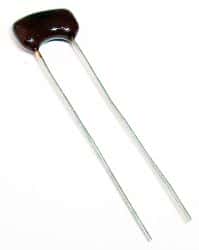
mica capacitorMica, a phyllosilicate, is a group of hydrous potassium/aluminum silicate material. It is a rock-forming mineral exhibiting a two-dimensional sheet or layer structure. That means it is possible to split mica into thin sheets. The biggest advantage of mica is the excellent stability of its electrical, chemical and mechanical properties. This property makes mica a suitable material for use as a dielectric when making highly stable and reliable capacitors. Silver-mica capacitors are useful at high frequencies, because of their low resistive and inductive losses and high stability over time.

Delved in India, Central Africa and South America, the most commonly used are the muscovite and phlogopite mica. While the first has superior electrical properties, the latter has a higher temperature resistance. Mica capacitors are expensive as the raw material composition has high variation, requiring inspection and sorting. Silver mica capacitors have sandwiched mica sheets coated or plated with silver on both sides. The assembly is then encased in epoxy to protect it from the environment.

Tolerance and Precision

Among all types of capacitors, silver mica capacitors offer the lowest tolerances, as low as +/-1%. In comparison, ceramic capacitors have tolerances going up to +/-20% and electrolytic capacitors can have more.

The design of a silver mica capacitor does not allow any air gaps inside. Additionally, the entire assembly is sealed hermetically from the environment. That allows the mica capacitor to retain its value over long periods. As the assembly is protected from the outside effects of air and humidity, the capacitance of a mica capacitor remains stable over a wide range of temperature, voltage and frequencies. The average temperature coefficient of mica capacitors is around 50 ppm/°C.

Losses

Mica capacitors have a high Q-factor. This comes from the low resistive and inductive losses exhibited by these capacitors. That makes them a suitable choice for use at high frequencies, but it comes at a price – silver mica capacitors are expensive.

It is difficult for manufacturers to make silver mica capacitors of larger capacitance value. Typically, this ranges from a few pF up to a few nF. However, they can stand high voltages and mica capacitors are usually rated for voltages between 100 and 1000 volts. Special mica capacitors are rated up to 10KV and these are mostly for use with RF transmitters.

Applications

You can use silver mica capacitors wherever the application requires low capacitances, high stability and low losses – especially in power RF circuits – requiring very high stability.

You can also use silver mica capacitors in high frequency tuned circuits such as oscillators and filters. Pulsed applications such as snubbers also use mica capacitors as they can withstand high voltages. If cost is an important factor along with tolerance and low losses, you can replace mica capacitors with class I ceramic capacitors. Ceramic capacitors are available at a fraction of the price of mica capacitors.

Mica capacitors are available as surface mount versions as well. This offers several benefits over radial or axial assemblies. By eliminating the leads, SMT designs offer a smaller device size that can be mounted directly to the PCB – resulting in a more compact design and greater mechanical stability.

Different Types of Light Sensors

Light falling on to the surface of a light sensor generates an electrical output proportional to the strength of the incident illumination. The sensor responds to a band of radiant energy existing within a narrow range of frequencies in the electromagnetic spectrum, which we characterize as light. These frequencies range from the infrared to the visible and continue to the ultraviolet region of the spectrum.

Most light sensors are passive devices for converting the light energy of the spectrum into electrical signal. Light sensors are also known as photo sensors or photoelectric devices, since they convert photons into electrons. We can group photoelectric devices into two main categories. One generates electricity when illuminated – such as photovoltaic or photo-emissive, etc. and the other changes their electrical properties in some way – such as photo-resistors or photo-conductors, etc. Accordingly, the following classification emerges.

Photo-emissive cells

These are formed from light sensitive material such as cesium. When struck by a photon of sufficient energy, the light sensitive material releases free electrons. As high frequency light contains photons of higher energy, they have a better chance of producing more electrical energy.

Photo-conductive cells

The electrical resistance of these cells varies when subjected to light. They are made of semiconductor material and the light hitting it causes photoconductivity, which controls the current flow through the material. Cadmium Sulphide is the most common material for making photo-conductive cells, such as the light dependent resistor or LDR.

Photo-voltaic cells

These generate an EMF or electromotive force proportional to the radiant light energy falling. Although similar in effect to the photo-emissive cells, these are made up of two semiconductor materials sandwiched together. Solar cells are the most common photovoltaic cells in existence.

Photo-junction devices

These photo-devices are made of true semiconductor devices such as PN-junctions that use light for controlling the flow of electrons and holes. Specifically designed for light penetration and detection applications, their spectral responses are tuned to the wavelength of light expected to be incident on the device.

Applications of light sensors

LDR photocell: The Cadmium Sulphide photo-resistive cell is the most common example of this device. The resistance of these cells when not illuminated is of the order of 10M ohms, which reduces to the level of 100 ohms when fully lit or illuminated. As the voltage drop across a resistor increases with its resistance value, an LDR photocell can generate different voltages in a potential divider circuit based on the amount of light falling on it.

Light activated switch: This is basically a dark sensing circuit, with a light sensor in series with a potentiometer forming one arm of a simple resistance bridge network and two fixed resistors forming the other side of the bridge. By changing the potentiometer, one can balance the bridge when the light sensor is illuminated, for example by sunlight. The absence of sunlight causes the bridge to unbalance and the resulting potential difference is amplified by an operational amplifier to operate a relay or a switch.

Today, it is common to find cameras that do not operate with a film, but with charge coupled devices that convert the light falling on them to an electronic image.

Which Raspberry Pi Should I Use?

Which Raspberry Pi or RBPi you will use is getting more and more difficult to answer as the family keeps growing. It was simple and straightforward when the RBPi first launched – there was only one model. Since then, with four major models to choose from, things are more complicated. However, this versatile beast comes in different specifications and you should select the one most fitting your requirements. Among the models available, here is a summary to help you decide:

RBPi Zero

This is the latest addition to the family. Although it is ultra-cheap, the RBPi Zero is definitely a fully functional single board computer. Compared to the first model of family, the processor used in the RBPi Zero is more than 40% faster. However, purchasing this variant compels you to make major compromises.

To start with, you will need adapters to use the mini HDMI and micro USB ports on the device. As there is no on-board Ethernet port, you need to use the single USB port. Although you can expand its functionality by adding a powered USB hub, the additions begin to detract from the major selling point of the Zero – its tiny footprint.

If the application does not require a fair amount of connectivity, is low-powered and for single-use, you may consider using the RBPi Zero.

RBPi Model A+

Although a full-sized version, this model also lacks the Ethernet port and has only one USB port. Moreover, it has only 256GB RAM that goes with the 700MHz processor. The price and lack of power makes it difficult to recommend the RBPi Model A+ for any application other than for specific ones.

RBPi Model B+

If performance is not a criteria and price is the only consideration, then the RBPi Model B is hard to beat. The model offers good connectivity as it has on-board Ethernet, four USB ports and a full sized HDMI connector. That makes the RBPi Model B+ more versatile than either the Model A+ or the RBPi Zero.

You can use it for any project that requires good connectivity, less than top-notch performance, and low power.

RBPi Model 2

This is the top-of-the-line model in the family and a surprisingly capable beast. With an updated chipset, a quad-core processor and 1GB RAM, the RBPi Model 2 makes a major difference in the large variety of Single Board Computers available in the market.

You can use the RBPi Model 2 as a media server for your network or use it for tasks of more intensive nature such as running a home surveillance system or playing games. It also allows you to explore platforms other than Linux – you can run the IoT version of Windows 10.

Even though the total power consumed by the RBPi Model 2 is below 1W, it uses significantly more power as compared to its predecessors. For example, RBPi Model 2 consumes more than 33% power drawn in by the RBPi Model B+ and five times more power than what the RBPi Zero consumes. Use the RBPi Model 2 for anything where you need good performance.

Check our other guides for information on Model 3.

How To Compensate Cable Voltage Droops?

Not only ordinary wires, but also USB cables can cause voltages to droop. This is evident if you have used an extra long USB cable and found that the device you were charging, such as your phone or tablet, was taking an extra long time to charge. The reason is the excessive voltage drop across the long USB or Universal Serial Bus cable.

Most chargers come with overcurrent protection. That means when the charging current exceeds a certain limit, the charger reduces its output voltage to prevent the charger from burning up. Moreover, when the charging current is high, the cable resistance causes the voltage at the device end to droop, increasing the charging time considerably. Since resistance increases with cable length, the voltage drop is also more with a longer cable. Hence, cable voltage droop has a negative impact on the operation of the system.

Proper charging and time taken is a critical design parameter for a device under load. With system load located at a distance from the output of the power supply, the absence of remote sensing may cause the voltage seen by the load to be significantly lower than desired. Contribution to the voltage droop is from thin circuit board traces, connector interface and cabling resistance. The situation gets worse when load currents are higher, decreasing the operational voltage at the load and causing possible erratic circuit operation.

A typical USB cable uses four wires of 24AWG each about a meter long and has a contact resistance of about 30 milliohms per contact. As a USB cable used for power transfer uses four connections (two on each cable end), the total contact resistance is 120 milliohms. The two one-meter wires of 24AWG have a total resistance of 166 milliohms. That makes the overall resistance of the USB cable to be 286 milliohms.

Typical converters are designed to supply a maximum output current of 2.1A. That means the voltage drop across the cable would be 0.6V when it is supplying maximum current. The voltage expected at the end of the cable would drop to 4.4V for a 5V set-voltage converter. This is much lower than the maximum lower-limit of most loads working at 5V and this may lead to potential issues with high-current loads.

Designers overcome this voltage drop by increasing the output voltage at the source. Instead of the fixed 5V, the converter would generate 5.6V, which after the 0.6V drop would present the necessary 5V to the load. They do this by monitoring the load current by adding a sense resistor in the path of the output current. A differential operational amplifier amplifies the voltage across the sense resistor and this voltage causes the output voltage to increase with increasing load.

As the load current increases, so does the output voltage of the converter. However, at the end of the cable, the compensated voltage is nearly a constant figure, representing a well-regulated voltage.

Compensating the output prevents the voltage at the load from drooping. This avoids potential system issues such as power cycling, latch-up conditions or decreased system performances.