Category Archives: Customer Projects

LED Indicator for the Raspberry Pi

Some projects are attempted not because they have any ulterior value, but simply because they are fun to do and involve learning for the uninitiated. The Raspberry Pi or RBPi is a low-cost, compact single board computer platform that came into being for the sole purpose of teaching youngsters how to program computers. However, its popularity has grown beyond its primary mandate. Making an indicator light come up for notifications is a simple fun project, which shows how to set up notifications and how to hook up an LED module to an RBPi.

To start with, for this project you will need a functional RBPi unit with Raspbian installed on it. In case you are new to RBPi, you can catch up with this tutorial on how to get started – it is essential that you have the basics covered before getting on. In addition to the RBPi unit, you will also need an LEDBorg module, available from PiBorg and a clear or frosted case for your RBPi. The clear/frosted case for the RBPi is not an essential item, but it conveniently hides the RBPi card and the LEDBorg module, while allowing the LED light to shine through – this offers protection as well as makes the project look neater.

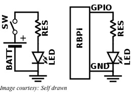
Strictly speaking, even the LEDBorg is not an essential item to use. You could connect a series resistance to an LED and use the combination instead. Using the LEDBorg only makes it easier for the project as it provides a compact unit that is designed to fit directly on the GPIO pins of your RBPi. If your RBPi is turned on, power it down, open the case and orient the LEDBorg module correctly before plugging it in.

While orienting the LEDBorg module, make sure the logo on the board comes closest to the RCA connector on the RBPi board, while the edge of the LEDBorg is flush with the RBPi board edge. While the case is open, take care to cover the indicator LEDs on the RBPi with opaque tape so as not to confuse the LEDBorg LED with the RBPI power and network indicator LEDs. Once the LEDBorg is plugged in and the extra LEDs are covered, you can close the case and power up the RBPi to move onto the next phase of the project.

Depending on whether your RBPi is a revision 1 or a revision 2, and the kernel version in use, you will have to download the specific software package for the LEDBorg from the PiBorg website. Now open up a terminal on the RBPi to download and install the package. This will give you the GUI wrapper for driving the LEDBorg through your RBPi. To check if the module is functional, pick any color in the demo mode of the software and test it. The only thing that remains now is to use scripts to change our LED into an actual indicator based on notifications.

For example, you may want to turn on the LED if there is rain forecasted in the weather report. Follow this tutorial to link up your LED with the weather forecast. The same tutorial will also tell you how to light up the LED if you have received mail in your Gmail account.

An Introduction to the Raspberry Pi GPIO

gpioThe highly popular, tiny, single board computer, the Raspberry Pi or RBPi has a row of pins along one of its board edges close to the yellow video out socket. These are its general purpose input/output or GPIO pins and one of its very powerful features.

The RBPi needs these pins to interact with the outside world physically. To simplify things, you can think of them as switches that you can control as inputs or that the RBPi can control as outputs. Of the 26 pins available, nine are for power and ground, while the rest of them (seventeen) are the GPIO pins.

You can set up these pins in different ways to interact with the real world and do fantastic things. It is not strictly necessary that the inputs come only from a physical switch. It might be the input from a sensor, a device or even a signal from another computer, for example. You can use the outputs for anything from turning on an LED to sending data or a signal to another device.

For example, if your RBPi is on a network, you can remotely control devices that are attached to it, while those devices can send data back. The RBPi is ideal for connecting to and controlling physical devices over the internet and that is powerful and exciting thing.

Playing around with the GPIO can be safe and fun, provided you follow some rules and instructions. It is very easy to kill an RBPi if you randomly plug wires and power sources into it – therefore the caution. You could also do a lot of damage if you connect things to your RBPi that use up a lot of power. For example, connecting LEDs to your RBPi is fine, but connecting motors are not. For those newly introduced to the RBPi, using a breakout board such as the Pibrella is a safer alternative than to use the GPIO directly.

For using the GPIO as an output, the RBPi replaces the power source and a switch in the external circuit. For instance, when an LED is to be lit up, generally a battery is used as a power source and a resistance is necessary to limit the current flow. A switch offers the means to turn the LED on or off. All these are connected in series for the circuit to operate.

To control the LED from an RBPi, you can safely omit the battery and the switch from the circuit. You can individually turn on or off each output pin of the RBPi. Additionally, when the pin is on or digitally HIGH, it outputs +3.3V and when it is off or digitally LOW, it outputs 0V. The next step involves instructing the RBPi when to turn the pin on and when to turn it off.

GPIO inputs on the RBPi require some more work. The RBPi senses an input signal on a pin based on whether there is adequate voltage present. The voltage presented by a sensor must be within levels specified for the RBPi to sense it as digitally HIGH or digitally LOW. Sensing analog or continually varying signals usually needs another interface called ADC or Analog to Digital Converter.

RemotePi: An Intelligent Infrared Remote Controlled Power Switch for the Raspberry Pi

When you have built a mediacenter system using the tiny single board computer, the Raspberry Pi or the RBPi, there is usually a hand-held infrared remote to manipulate the various controls. However, using the remote to switch off/on the mediacenter system does not switch the RBPi. Adding a RemotePi board lets you switch on/off the power of the RBPi safely with the remote or a push button.
There are two versions of the RemotePi board – one that fits the RBPi Models A+ or B+, and another that fits RBPi Models A or B. Although electrically similar, RBPi Models A+/B+ are different from Models A/B – the mounting holes and connectors are differently placed. Therefore, you must select the RemotePi board to fit your current RBPi model.

Additionally, the RemotePi board comes in two variants. The first has the IR receiver and LED integrated on it, while the second variant sports an external IR receiver and LED connected by a cable. The second variant is useful when you want to mount the RBPi and RemotePi out of sight, leaving only the IR receiver and LED visible for the users.

The RemotePi works by re-routing the power to the RBPi, instead of feeding it directly. On the board, a micro-controller manages the power line to the RBPi. Depending on the command received from the push button on the board or the infrared remote control, the micro-controller switches power on or off for the RBPi.

However, when switching off the power to the RBPi, RemotePi does not cut off the power immediately. Instead, it sends a notification to the RBPi via a signal on its GPIO port. The RBPi monitors this signal on the GPIO port continuously via a script running in the background. Once triggered, the script initiates a clean shutdown of the OS and thereby, prevents data corruption. Once the shutdown is successful, RemotePi then proceeds to cut off the power completely to the RBPi.

When the RemotePi has to switch power to the RBPi from an infrared remote control, you must teach the unit to recognize the type and button preferred. For this, you let the RemotePi enter a learning mode and then point your remote control towards the infrared receiver on the board. Now press the preferred button on the remote you would like to use in future to control power to the RBPi and the RemotePi will remember the button. For using a different remote or button, simply repeat the process.

Another feature of the RemotePi is that you can teach it to use one button to power off the RBPi and use another to switch the power back on. Apart from controlling power, the RemotePi board will forward any received infrared signal to the RBPi. Therefore, you can use the remote control for the mediacenter as well as use LIRC for the RBPi.

RemotePi prevents data corruption on the RBPi with sudden power outages. Additionally, you can reboot the RBPi to clear memory leaks or for automatic updates. It does not occupy a USB port and is totally compatible with the simple GPIO IR receiver.

Control your computers from anywhere with the Raspberry Pi

If you are one of those who often need to use the home computer from a remote location, then you need a Web-based application that can power your home computers up or down. For example, you may have a specific file or folder on your home computer that you urgently want to access but cannot do so because you are in a different location.

Keeping the home computer always powered on is not a great idea, even though it allows remote connections when required. For one, an always-on computer consumes power unnecessarily. Additionally, if there is a crash, there is no way you can get it up running again from your remote location. This is exactly what Martin Peters faced when he devised a hardware-based solution to cut the power down to his home computer and put it back up again when necessary.

What Martin realized that he had to have at least one computer always on and connected to the internet, to be able to control the others from a remote location. He hit upon the cheapest and lowest power consumption computer – the Raspberry Pi or the RBPi. Additionally, this tiny single board computer comes with an Ethernet port and some General Purpose Input Output or GPIO. The Ethernet port allows the RBPi to connect to the Internet and the GPIO allows controlling additional electronic circuitry.

Martin used the GPIO on the RBPi to control electronic circuitry on a circuit board he has custom made, see details here. This allows him to cut the power to his home computer, press its power switch and read the state of its power LED. For doing this, he has designed a web-based user-interface with which he wraps those GPIOs. The user-interface updates in real time and displays logs along with the power LED status.

The C++ widget-oriented web toolkit used by Martin is called Wt. The toolkit handles updates with a very simple method and even provides a native library called wiringPi to handle the GPIOs of the RBPi.

The GPIOs on the RBPi are very sensitive and can easily be damaged if more than 3mA is drawn from them when in output mode. The best solution Martin found was to isolate those using opto-isolators. Since Martin wanted to control many computers from the RBPi, he decided to place all the opto-isolators close to the RBPi and all the switching on the PC side. That meant each PC was to have a PCB and all the circuits could be connected with an Ethernet cable.

Keeping a relay to cut the power to the computer would require an additional 12V power supply to operate the relay. Instead, Martin accessed the green wire on the secondary side of the ATX power supply unit. When the computer’s motherboard wants to wake up, it shorts the green wire to the ground, which signals the ATX PSU to start supplying voltage to its other pins and the entire computer boots up.

Martin used a MOSFET in series with the green wire. He tied the gate pin of the MOSFET to the +5V (violet wire) of the ATX PSU via a 10K resistor. Pulling the gate to ground using an opto-isolator gave Martin complete control of the ATX PSU.

Add Bluetooth to any speaker

using bluetooth on any speakerMany of us have old unused powered speakers stashed away somewhere. Even if they were to be used, long snaking wires would have to be laid, depending on how far away they were to be placed from the amplifier. In this era of Bluetooth, we are spoiled by the ease with which we can connect – without wires. In fact, Bluetooth allows us to connect not only two phones, but also computers, mice, keyboards, tablets, headphones, fitness trackers and so many more gadgets. However, Bluetooth audio remains the most popular application among all the above.

Bluetooth audio allows you to pair a speaker or speakers with any device, such as a phone, computer, tablet or any other, so that you have an audio connection – sans wires. Different types of Bluetooth speakers are available in the market. However, good Bluetooth speakers are quite expensive. The only advantage with these wireless Bluetooth speakers is that they will not be tethered by wires – their performance however, is not going to improve.

Therefore, if you have old speakers that still perform very well, upgrading them to work without wires will be worth the small amount of expenditure required to add Bluetooth to them. Once installed, the Bluetooth receivers in your speakers will pair with any Bluetooth enabled device. This will enable you to stream any audio from anywhere to your speakers.

Depending on your needs, shop for the right type of Bluetooth receivers from sites such as Amazon, eBay and others. Some have optical audio connection, while others come with RCA plugs for the left and right channels. Almost all will have an LED that lights up when the unit is paired to a device. The units run on 5V, so a USB power supply will do, while output is taken through a 3.5mm stereo jack.

Setup is simple – connect the Bluetooth receiver’s audio out to the audio cable of your speaker, or to its auxiliary input, if the speaker has them. Next, power up the unit and now all that is left is to pair the unit with a Bluetooth device.

As soon as you plug in the power to the receiver, it will start broadcasting its identifier. Open the Bluetooth settings on the device you prefer and connect. If you have a low-end device, only one pair can remain connected at a time. To switch sources, you will have to disconnect the current pair first before pairing another. Some high-end devices can store up to eight different audio sources, allowing easy switching.

The sound quality of an audio system depends primarily on the quality of the source and then on the quality of the amplifier and speaker combination. Addition of the Bluetooth receiver in this chain does not detract much from the listening pleasure. In fact, you will hardly notice any difference between Bluetooth streaming audio wirelessly and speakers connected directly with wires. The advantage with Bluetooth connection is that you can place your speakers more than 30ft away from the source.

Therefore, if you have a pair of powered speakers lying around unused, you can upgrade them with Bluetooth. You will be surprised at how much better they sound compared to the tinny sound from your mobile.

Raspberry Pi Lights up a 64×32 RGB LED Matrix

When you want to make a video wall such as those found on the sides of buses and bus stops in New York, you need a panel with a matrix of LEDs. These are very handy for displaying short video clips or animation. Adafruit has quite a few of them in different matrix sizes such as 8×8, 8×32, 16×24, 32×32 and 64×32. The last one is available in pitches of 3, 4, 5 and 6 mm.

LEDs on the panel are placed close together in a 3 mm pitch, so that you can appreciate it from up close. With the matrix being made of bright RGB LEDs, you have a 160-degree wide-angle view and the panel looks great both in either ambient light and indoors. You can use panels with a larger pitch if you want it to be read from still farther.

In the matrix on the panel there are 2048 gleaming RGB LEDs arranged in a grid of 64×32 in front. The backside of the panel sports a pair of IDC connectors – one of them is for input and the other for output. You can drive the display with a 1:16 scan ratio when the two connectors are chained together. For this, you need 12 numbers of 16-bit latches.

Along with each panel, Adafruit provides an IDC cable, a plug-in power cable, four mounting screws and mini-magnets (for mounting quickly on a magnetic base). You will have to buy the regulated 5V power supply unit separately. The panel consumes about 4A. The panels need 13 digital pins of which 6 bits are required for data and 7 bits for control. That makes the panels perfect for being driven with the tiny, inexpensive, credit card sized SBC, the Raspberry Pi or RBPi.

You cannot drive these displays by FPGAs or any other processors using high speed, as there is no PWM control built into the panel. Instead, you need to refresh the display manually by redrawing the screen repeatedly. For example, for displaying a 4096 color image (12-bits), you will require about 3200 bytes of RAM for buffering and the process will take up about 40% of CPU time. Adafruit provides support with complete wiring diagrams and library code for drawing pixels, circles, rectangles, lines and text.

An RBPi cannot directly drive the RGB LED display matrix directly. The GPIO pins on the RBPi cannot provide the necessary drive. Moreover, signals from the RBPi will have to be level shifted as the panel works off 5V, as compared to the 3.3V for the RBPi. Adafruit has a drive board – the RGB Matrix Hat. This sits on the RBPi and makes it easy for the RBPi to control the RGB matrix for creating a colorful scrolling display.

It is very simple to link up the RGB Matrix HAT with the panel on one side and the RBPi on the other. Plug in the HAT on to the RBPi, plug in the IDC cable and turn on the respective power supplies. Now, run the Python code from Adafruit. The 5V, 4A wall adapter plugs into the HAT, which protects against under, over and negative voltages to the display.

Raspberry Pi accessories from Microstack

If you are looking for accessories for your tiny, credit card sized single board computer, the Raspberry Pi or RBPi, you now have a series of them from the distributer element14. This Microstack range of accessories allows all levels of users to create and prototype physical devices simply and quickly. Most popular among the Microstack accessories are the GPS positioning and accelerometer.

Microstack claims that its modules are the “building blocks for the Internet of Things for All”. The original designers of PiFace Digital and PiFace Control and Display accessories for the RBPi have come together to create Microstack. In fact, building on PiFace, Microstack now offers several types of connected-device possibilities for the RBPi.

Microstack offers a family of stacking accessory boards that a compact and reusable. They offer a common form factor, interface connections and software. All the accessories for the RBPi are built on a platform-specific baseboard called the adapter board.

The GPS module from Microstack is a simple and easy plug-and-play solution. You can use this module for projects requiring GPS positioning for creating geo-location awareness. The GPS module has several worthwhile features. Not only can the module log data in its standalone mode, it allows the RBPi to keep time in a highly accurate and globally synchronized manner. The Microstack GPS module is one of the most complete and advanced modules and it sports an embedded high sensitivity 15×15 mm internal patch antenna with an external socket.

The antenna switching function is automatic as the GPS module has antenna detection feature along with short circuit protection. For better sensitivity, the module has a built-in LNA. The advanced AGPS technology works with an intelligent controller of periodic mode that does not require any external memory. Microstack has provided LOCUS as an innate logger solution that works independently without host and external flash. The GPS module comes with anti-jamming features that sports Multi-tone Active Interference Canceller with 66 acquisition channels and 22 tracking channels. You can combine it with other Microstack add-ons to provide radio links for supporting remote telemetry.

The Accelerometer module from Microstack is also a simple plug-and-play device for the RBPi. It is useful where measuring acceleration is necessary for projects such as tracking and motion, game and tilt sensors and robotics. The module is based on MMA84910, a simple, low power, three-axis low-g accelerometer that offers multi-range 14-bit at +/- 8g resolution.

With a 1.95-3.6 V supply voltage range, the Accelerometer module consumes only 400 nA per Hz, but provides data at ultra-high speeds in about 700µS. Its 14-bit digital output has a sensitivity of 1 mg/LSB with a +/- 8g full-scale range. The Microstack framework compatible accelerometer module has 45° tilt outputs for its three axes and you can link it to your RBPi with the I2C interface.

You can use the Microstack modules as standalone or integrate them into full custom PCBs. Therefore, the modules provide a solution right from prototyping to production. These modules offer powerful building blocks that cut down on the development time with support software and easy installation.

Raspberry Pi drives photon elephant

You are looking for the best way to control your 3D printer and turn it into a smartprinter. If you are not averse to using a browser-based control panel that will allow you to stream from a webcam, start, pause and resume print jobs while slicing your STL files, you may consider the Photon Elephant.

The Photon Elephant uses the tiny, low-cost, credit card sized, single board computer – the Raspberry Pi or RBPi – to drive the motor controllers of your printer. A conventional SDK or Software Development Kit uses the GPIO pins of the RBPi for the controls. This is all open-source, which means you can tinker with it to your heart’s content. For example, you may want more than what the standard 5-motor controller has to offer. With the Photon Elephant, you can have more time innovating rather than figuring out what makes the firmware tick.

Photon Elephant provides you a bunch of software and hardware based on the RBPi that controls your 3D printer. Printers available in the market typically use an Arduino, without an operating system, to manage the sensors and motors, while the RBPi is used to send it commands. Photon Elephant puts the power of Linux directly into your printer by eliminating the Arduino.

Anyone can build on the simple but powerful Photon Elephant platform. The platform makes it easier to create new and exciting types of 3D printers. Available open source solutions for controlling 3D platforms tend to be out of date and tedious. With the Photon Elephant, the next generation of 3D printers will be more flexible to control.

Entrepreneurs, students, makers and hackers anyone can easily use the Photon Elephant. It handles the entire stack and controls everything from sensors, motors and the User Interface. If you are looking for the simplest solution for getting your printer up and running, Photon Elephant is for you. Additionally, with the Photon Elephant SDK, you have the easiest platform you can build upon.

There is no firmware to be flashed. Use the pre-programmed image on the SD card and plug it in to fire up your RBPi. All you require to do is to connect any compatible printer to the Photon Elephant companion board and you can start using your printer. All the different firmware such as the slicer and printer managers talk seamlessly to one another. Therefore, you simply have to open up a browser on any device and start using the printer over Wi-Fi.

The 3D printing industry is moving forward very rapidly and printers become outdated very quickly. Currently, Photon Elephant is able to support Cartesian RepRap style of printers only. Very soon, Delta printers will also be supported. The SDK is flexible to take on almost any printer methodology.

Flexibility is extremely desirable considering how difficult it is to predict the direction the 3D industry may be taking. There is no sense in spending time in modifying the firmware directly on a chipset as it may become useless by tomorrow. The flexibility of the Photon Elephant SDK helps the user keep up with the industry, as it is very easy to add newer features to the current design

Let Raspberry Pi do your Calling and Answering

In certain projects or experiments where you are monitoring an entity such as temperature or pressure, it is impractical to be physically present for any length of time. However, it may be important for you to know when the measured entity breaches a high or a low set point. For example, if something is not working out as it should – say temperature or humidity too high – you may wish to start or control another activity rather quickly to compensate.

In such cases, the handy, credit card sized single board computer, the Raspberry Pi or RBPi can be of immense help. RBPi can call, sms or inform you via web-interface, in case things are tending to go beyond their limits. Although sms and web-interface work equally well, for cases that are more important a call gets more attention than the others do.

When receiving a call, you expect the other party to speak up. Programs such as eSpeak and Festival endow an RBPi with capabilities of synthesized speech. Both tools allow you to cache speech as wav-files. eSpeak is more adjustable and creates wav files a bit faster than Festival; however, their performance is similar. You can select any one of the programs depending on your preference and install it with a ‘sudo apt-get install …’ command.

For making calls, it is simpler to use a sip/voip based system. Here again, you can select between two capable tools – PJSIP or Linphone. Of the two, Linphone is difficult to include into an application script. PJSIP has a command line interface and provides a powerful api that you can use within your own sip-based project. However, you will need to download and compile it for Raspbian.

After compilation, you may find some echo or jitter when making normal calls to another phone. To get rid of these, you will need two other tools – sipcall and sipserv. Sipcall will help you to make a completely automated call to a specified number using a text to speech converter. That makes it very useful when using via bash-scripts. For example, you can ask it to check the state of a sensor and place a call if a critical threshold is reached. On the other hand, Sipserv is more like a service, where you make a call to query information and/or execute a command via phone. Of course, your sip-provider must support inbound DTMF. Both tools are available here, but you will need the pkg-config-package tool to compile them.

The original author has also created simple bash-scripts that can check the actual load and place a call if the load is found too high. For stopping/starting the service available, he has provided a simple configuration and a bash-script that you can use for Sipserv. Readme files and general info is available for the user. For more details, refer here.

Although the tools are rather ‘proof of concept’ than a final product, they work well. The author permits changes and extensions to his original work and invites suggestions on any improvements, more especially for the current sound problems of echo and jitter.

Integrate your Raspberry Pi to the Hackable Roomba

You do not find many robots in the consumer arena, unless it is the AVA 500, the telepresence robot from iRobot. Users can simply specify where they want AVA 500 to be and it automatically navigates to the destination without requiring any human intervention. It has advanced mapping technology combined with a real-time view of the environment. Another simpler consumer robot is Roomba, from the same company, iRobot.

iRobot has turned the highly successful Roomba 600 robot into a hackable Create 2 version. This is very useful for K12 and college level STEM education, because Create 2 can be programmed via a laptop, an onboard Arduino or a Raspberry Pi (RBPi). Although both AVA 500 and Roomba are Linux based, unlike the more sophisticated AVA 500, Roomba 600 was a modest, vacuuming robot, based on a simple Motorola HC12 micro-controller.

Create 2, the modified Roomba 600, is not meant for vacuuming, as iRobot has eliminated all the internal vacuuming equipment. That leaves Create 2 with plenty of space inside for adding custom hardware components. You can easily put in an RBPi there, using pre-programmed routines to control the bot. Other alternate methods of direct control are tethering Create 2 to a laptop via the serial Mini-Din port using a serial-to-USB cable.

Based on the original Roomba 600, Create 2 is a round, 3.58-Kilo robot, measuring 340 mm in diameter and 92 mm in height. The market has several models of the Roomba robot, but Roomba 600 is the cheapest. iRobot offers 3D printing files that help you in adding electronics and peripherals to Create 2. They provide instructions for replacing the bin with a cargo tray that you can 3D print. They also supply a faceplate drill template.

Rechargeable batteries on the Create 2 allow a three-hour run before needing a recharge. As with the original Roomba 600, Create 2 will also return to its charging dock when it is time for a recharge. Sensors, such as IR transceivers on Create 2 enable it to escape cul-de-sacs and move around obstacles.

To interface with the Motorola MCU and related components, Create 2 comes with a programming environment, the Roomba OI or Open Interface. With the Roomba OI, a user can program the behavior, sounds, movements and read its sensors. The OI provides several commands for the sensors, cleaning, song, actuator and mode settings.

RBPi Model A is the most suitable for controlling Create 2 as you can run it off the serial connector of the robot. Power requirements for the Model A and its camera are just within the headroom of the on-board thermal resettable fuse of Create 2. It is also possible to work with RBPi models A+, B or B+; however, you will have to power them independently.

The RBPi will need an SD card of at least 4GB, pre-installed with the Raspbian Linux. Other hardware that you will require are an RBPi camera board, a switching DCDC converter, a micro-USB male cable, a 5V to 3.3V level converter and a USB to Wi-Fi module. iRobot provides several programming samples and starter projects with varying levels of difficulty.