Category Archives: Customer Projects

Digital Isolators vs Optocouplers

Industrial equipment may need to operate in a region of strong electromagnetic fields. There can be a sudden surge in the voltage applied to the equipment, which may be hazardous to the user and the gear. It is crucial that you incorporate a reliable isolation system to take of these issues.

Until very recently, the optocoupler was the only practical choice in providing safety isolation for manufacturers of medical and industrial isolated systems. The arrival of digital isolator has however, changed the situation greatly.

Digital isolators offer several advantages over optocouplers. They are more reliable, cheaper and have greater power efficiency compared to the optocouplers.

It is important that you understand the three vital aspects of an isolation system. These are the insulation material, the structure and the method of transfer of data.

Insulation Material

Typical insulation materials are silicon dioxide wafers and thin film of polymers. Optocouplers use polymer films. Digital isolators make use of a particular form of polymer called polyimide. This material serves to increase the efficiency of isolation systems.

Silicon Dioxide is not a very suitable material as an isolator. While you may increase the thickness of polyimide to increase the insulation, you cannot adopt the same method for silicon dioxide. Wafers thicker than 15 micrometers may crack during processing.

Structure

Digital isolators use either transformers or capacitors to transfer data across the isolation barrier. A transformer system has two coils placed side by side. Current flowing through a coil (called the primary coil) gives rise to a magnetic field in the space surrounding the coil. This induces a current to flow in the other coil (called the secondary coil).

A capacitor consists of two metal plates with the space between the plates filled with a non-conductor.

Optocouplers use light emitting diodes (LED) for data transmission.

Transfer of Data

The LED in an optocoupler turns on for logic high state and turns off for logic low state. The device consumes a significant amount of power when the LED is on. Digital isolators do away with this undesirable aspect. The sophisticated circuitry in the system encodes and decodes data at a rapid pace so that the transmission of data involves less power consumption.

A digital isolator using a transformer for data transmission transfers the data from the primary coil to the secondary coil during the pulses of current driving the transformer.

A digital isolator may use radio frequency signals as well, in a fashion similar to the way an optocoupler uses light from an LED. However, since a logic high state causes a continuous transmission of radio frequency signals, this method uses more power.

Digital isolators with capacitors have an advantage in that they consume lower currents for creating coupling electric fields for data transmission.

Ensuring the Correct Combination

It is important to use the right insulating material and the apt method for data transfer depending upon the application.

Since polymers provide more than adequate insulation, they are suitable in most applications. Polyimide insulation is particularly suitable for equipment used in healthcare and heavy industries.

Concerning data transfer, capacitor isolation is adequate for situations requiring just functional and not safety isolation. Isolation systems making use of transformers will serve the purpose of safety as well as functional isolation.

Some Frequently Asked Questions about Raspberry Pi

Q. What is a Raspberry Pi?

A. The Raspberry Pi is a low cost, tiny computer, about the size of a credit card. You can plug your keyboard, mouse and your TV into it, and use it just as you would use a PC. It is capable of playing games, word-processing and working with spreadsheets. You can even watch high-definition video. The composite and HDMI out allows you to connect to any old analog TV, a digital TV or to a DVI Monitor. It is a wonderful device for kids to learn programming.

Q. What are the different models of Raspberry Pi available?

A. As of today (August, 2013) there are two: Model A and model B. Model A has 256MB RAM and one USB port. Model B has 512MB RAM, 2 USB ports and one Ethernet port. When you buy the Raspberry Pi, you get only the board. No SD card or power supply is included, but you can buy them separately. Pre-loaded SD cards are also available.

Q. What are the physical dimensions of the Raspberry Pi?

A. The Raspberry Pi dimensions are 85.6x56x21 (mm) or 3.37×2.21×0.827 (in.), with a small overlap as the connectors and the SD Card project over the edges. The Raspberry Pi weighs about 45 gm.

Q. What is the SoC used for the Raspberry Pi?

A. The SoC or System on Chip is a Broadcom BCM2835. This contains an ARM1176JZFS processor running at 700 MHz, with floating point and a Videocore 4 GPU. The GPU is capable of Blu-ray quality playback and uses H.264 at 40MBits/s. The fast 3D core is accessed using the supplied OpenVG and OpenGL ES2.0 libraries.

Q. How powerful is the Raspberry Pi?

A. The GPU or the Graphical Processing Unit operates with OpenGL ES2.0 and the hardware-accelerated OpenVG libraries, providing 1080p30 H.264 high-profile decode.
The GPU can provide 1Gpixel/s, 1.5Gtexel/s or 24GFLOPS of general-purpose compute along with several texture filtering and DMA infrastructure.
In real world terms, the performance is similar to a 300MHz Pentium 2; however, Raspberry Pi provides much swankier graphics. Overall, the graphical capabilities can be equated to an Xbox 1 level of performance.

Q. Will the Raspberry Pi blend?

A. Yes, extensive virtual simulations have been carried out, there were no failures.

Q. Is it possible to overclock the Raspberry Pi?

A. Most of the devices run comfortably at 800MHz. The latest operating system has options of changing the options for overclocking on the first boot. If you run “raspi-config” you can change the options again at any time, and your warranty stays intact. However, these settings are experimental and not every board can be expected to run stably at the highest setting. To restore stability, try reducing the settings for overclocking.

Q. How do you boot the Raspberry Pi?

A. You need a pre-loaded SD card to boot. After the initial boot, a USB HD can “take over”. The root partition on the SD card must contain the operating system. Currently Debian Linux is the default distribution, but you can use any other ARM Linux distro available on the downloads pages.

Q. What are the power requirements of the Raspberry Pi?

A. The device is powered by 5V from the micro USB. To switch on, simply plug in the USB, to switch off, remove the power.

Let Raspberry Pi Make It to the Movies through XBMC

The Raspberry Pi is capable of HD video. Won’t it be great if you could playback your Blu-ray movie collection through Raspberry Pi on to your HD TV or monitor? That would be possible if you knew how to let Raspberry Pi run XBMC.

What is XBMC?

XBMC is a software media player and entertainment hub, and the best part is you do not need to pay anything to get it, as XBMC is free and open source (GPL). As a media player, XBMC has almost everything you will need, right from TV and remote controls, to support for digital media files from local and network storage media including the internet. You can play and view most digital media files such as podcasts, music and videos.

There is not much that XBMC misses. You get to play all your music files in mp3, flac, wav and wma formats. You can watch movies in all the main video formats including streamable online media. You can keep track of your progress of season views and episodes of TV shows. You can import pictures into a library for browsing as in a slideshow, and you can record live TV all from the nice GUI interface that XBMC has.

Step 1: Download XBMC

You will need to download an image of XBMC, which is available as “debian-xbmc-24-04-2012.zip” and you can get it here. Unzip the file to get to the image.

Step 2: Write the Image on to an SD Card

If you are on Linux or OSX, open up a terminal and navigate to the folder containing the downloaded image. To write to an SD card, you have to enter the following command –

dd bs=1m if=debian-xbmc-24-04-2012.img of=/dev/rdisk1

Note that ‘/dev/rdisk1’ depends on the type of PC you are using.

If you are still on Windows, you need the Win32DiskImager utility program to write the image to the SD card in the device box.

Step 3: Make Space on the SD Card

The image written to the SD Card will be about 2GB, leaving about 60MB free space. This is not enough for XBMC to operate properly. Use Gparted, which is the Debian partition editor to expand the free space. Assuming you have a 16GB card on which you installed the OS and XBMC, there is still 13GB space left over. Go into Gparted, and expand the Linux swap partition to cover the 13GB. That will allow XBMC to use the free space.

Step 4: Start Action

Plug in the SD card into your Raspberry Pi, and boot it up. At the command prompt, type –

XBMC

and you should be able to see the following –

Note that XBMC is still an alpha release, and is somewhat fragile. It might lock up or not start at all. This is expected and you may need to restart Raspberry Pi over again to get XBMC play properly.

Try out all your music, video and other programs including your favorite TV shows, and you will be surprised at the quality of the output from the combination of XBMC and Raspberry Pi.

Raspberry Pi projects to inspire you!

In How Many Ways Can You Use Your Raspberry Pi?

Many of you who already have the tiny Linux PC – the RaspBerry Pi – affectionately also known as RBPi, are already using it in your own way to write and test code and to build controllers. The Raspberry Pi is a stripped-down Linux computer, running an ARM-Based CPU, with a graphics processor and many pins and ports, which you can use. We present here many extraordinary ways that owners have Raspberry Pi developed new projects.

Well, taken straight out of its packing, you can plug your TV into Raspberry Pi, connect a keyboard and try some of casual games, video streaming and word processing. All this must have become pretty mundane for Simon Cox after sometime, since he decided to build a supercomputer out of many Raspberry Pis. The computer engineer from UK’s University of Southampton tied 64 Raspberry Pis together. His 6-year old son built the rack for the supercomputer with his LEGO set!

Have you ever thought of mixing music, vegetables, wordplay and Raspberry Pi? Not likely, but Scott Garner has. On his BeetBox, you can play drumbeats on real beets when you touch them. He has used capacitive touch sensors for communicating between the beets and his Raspberry Pi. His only complaint is that the beets dry off and have to be replaced.

If Raspberry Pi is a Linux computer, surely it can be used as a palmtop. A similar thought must have prompted Nathan Morgan to build his Pi-to-Go Palmtop. Sporting a 640×480 display, a touchpad, support for HDMI, Bluetooth, Wi-Fi and a 64-GB solid state drive, it is a perfectly portable Raspberry Pi. However, some of you may not find it to be the thinnest or the lightest, but it is enough as a proof of concept to its maker.

Beer and Raspberry Pi may not be an obvious match, but that did not deter a company Robofun Create in making a QWERTY keyboard from 44 beer cans from a Prague-based brewery. If you are over 21, you are allowed in the bar and you can tap the tops of the beer cans to let Raspberry Pi produce the corresponding alphabets on a plasma screen overhead. Of course, the alphabets are also marked on the tops of the beer cans.

Movies such as “The Life of Pi” can also be inspiring. FishPi is planning to set Raspberry Pi adrift in a boat that will be crossing the mighty Atlantic. Raspberry Pi will not be floating idly, but has to control the boat’s navigational system. In short, Raspberry Pi will be the captain, navigator and sailor for the 20-inch long boat. Additionally, it has to collect scientific measurements for which it will be powered by a 130-watt solar panel. We wish Raspberry Pi all success on its solo sailing trip.

Like most people who buy nice things on impulse, such as an Raspberry Pi, are stuck for want of a suitable project. Jeroen Domburg had the same problem, until he came up with the Teeny Tiny Arcade. His is probably the smallest gaming cabinet built in an arcade style. Jeroen cut the plastic with laser to make his cabinet and it has a 2.4-inch TFT Display.

Let Your Raspberry Pi Take Pictures of the Earth

How About Letting Your Raspberry Pi Take Pictures of the Earth?

Many many years ago, before cameras came to be associated with lenses, people captured images on film using a pinhole on the camera. This technique is still in use today. It’s called heliography and it requires long to very long exposure times – sometimes as much as 24 hours to six months. The results are rather stunning, as you can see.

Unless you have photography as a hobby, you may not be able to spare much time and may not have equipment suitable for heliography. However, taking pictures of the earth is quite an exciting project, and since you have Raspberry Pi, why not let the tiny Linux computer do it?

That is exactly what Dave Akeman planned to do. He created the Raspberry Eye-in-the-Sky project that sent Raspberry Pi and a bunch of components out into the atmosphere where the weather balloons go and burst themselves. The payload consisted of a Raspberry Pi, a camera and a tracker, powered by a few AA batteries. The pictures, taken while the camera was in the sky, are spectacular and amazingly crisp.

Dave changed the regulator on the Raspberry Pi and modified it so the computer could work on 3V instead of 5V, to allow the batteries to last longer. He embedded the entire electronics in a foam replica of the Raspberry Pi logo, with the camera peeping out from the bottom. The foam was for softening the landing of the package when it hit the ground after the balloon burst. Dave also put in a parachute so the package would come down smoothly.

Dave had to take permission from the CAA for the Hydrogen balloon that would carry his Raspberry Pi camera payload into the atmosphere. He used the latest Pi camera software and changed the code to make it take three types of images each at about one minute interval. One small image is taken for the first radio channel, one medium image for the second radio channel and one hi-resolution image is stored on the SD Card onboard. Additionally, Dave configured the camera to work in matrix-metering mode instead of spot metering, as this gave better resolution images.

The balloon and its camera payload went up one sunny morning, near Tetbury, UK. People from France, Holland and Northern Ireland monitored the Raspberry Eye-in-the-Sky broadcast. The image quality throughout the 3-hour flight time was excellent. The flight path, with the wind guiding it, had quite a few changes of direction and some loops. The package went up to about 24.5 miles in height finally landed near the city of Swindon about 22 miles away from Tetbury.

As the launch was delayed by more than 2 hours, the Raspberry Pi package missed the original predicted landing spot, since the wind pattern had changed in the meantime. In addition, a resident of Swindon found the package as it landed near him, and took it home. He then called up Dave after finding his telephone number on the package. That solved the initial mystery as to how the Raspberry Pi package travelled to another location after it had landed.

How to measure temperature with a Raspberry Pi

Looking for another project to make with a Raspberry Pi? You can use your Raspberry Pi to measure temperature. Not only at a single point, but also at maximum of 20 points simultaneously. Of course, you will need 20 individual sensors for doing that. Raspberry Pi will poll all the 20 sensors one after the other, and read the temperature from each of the sensors.

If you are wondering how complicated it would be to wire up 20 sensors to the Raspberry Pi, you can relax, since you need only three wires in all. One of the wires will carry power to the sensors, one wire will be the ground or return path and the third wire is a unique 1-wire interface to control the sensor and to read the temperature measured by it.

This wonder sensor is a High-Precision 1-Wire Digital Thermometer, DS18S20, with a measurement range of -55°C to +125°C (-67°F to +257°F), a thermometer resolution of 9-bits and an accuracy of ±0.5°C from -10°C to +85°C. Maxim Integrated makes this thermometer and the smallest size is a little larger than a matchstick head (TO-92).

Not only can this tiny fellow read the temperature, it stores them in its non-volatile memory and can present them either as °C or as °F. You can set temperature limits in its memory and DS18S20 will tell you when the temperature it is monitoring goes beyond the programmed limits. You can use this thermometer with the Raspberry Pi to control thermostats, industrial systems, consumer products or any thermally sensitive system.

At this point, you may be wondering if there is only one single wire for all the 20 sensors, how is the Raspberry Pi able to differentiate the twenty temperature readings. Maxim has programmed each of the sensors with a unique serial number, and when Raspberry Pi wants to read the temperature from a specific sensor, it simply asks for it by the serial number of that sensor. Only the sensor whose serial number the Raspberry Pi queries, sends the temperature data, all the others remain silent.

The Raspbian Linux distribution that you are using in your Raspberry PI already has all necessary kernel modules installed for accessing the 1-wire bus. The programming details are rather simple and you can refer to them here.

What else can you do with a DS18S20 and Raspberry Pi? You may be measuring temperature at a remote place, or there is no space for the extra power supply to the DS18S20. So, instead of supplying power separately, you could make DS18S20 “steal” power from the 1-Wire bus. For this, you must connect the VDD pin of the DS18S20 to ground. According to the datasheet, do not use the parasitic mode for measurements above 100°C, as the DS18S20 will not be able to sustain communications.

If you have programmed temperature limits for some of the DS18S20s, they will raise a flag if the temperature they are sensing goes beyond the set points. By polling for the flags, Raspberry Pi can know, which sensor is sensing temperatures beyond its set point.

How to solder – an illustrated guide

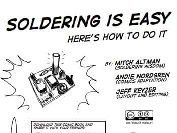
Guide to learning to solderWe love when we come across electronics info and guides that others are sharing freely – and especially those that encourage others to share their knowledge and work.

For example…here is a fully illustrated guide to learning how to solder which was done by the fine folks at http://mightyohm.com. They’ve created a super guide with all the basics covered as well as some interesting tips and tricks that can make your soldering experience a little better. This would be a great staple for some basic electronics classes.

To see the full soldering guide, click on the image above.

Thank you to the creators of this comic book: Mitch Altman, Andie Nordgren and Jeff Keyzer. Great work!

How to wipe a hard drive clean

If you are donating, disposing of or selling anything that contains a hard drive, chances are that drive should be wiped clean before it leaves your hands. Even if the hard drive has failed, special equipment can read a hard drive which could expose your private and confidential information to the next owner.

So what should you do before your dispose of your equipment with a hard drive? There are several methods that are recommended by the experts. Here is an explanation of two of them:

1 – Destruction:
According to the National Institute of Standards and Technology Special Publication 800-88, “Destruction of media is the ultimate form of sanitization.” Some methods to destroy a hard drive include pulverization, incineration, melting, and shredding however it should be noted that it is recommended that you never burn a hard drive, put a hard drive in a microwave, or pour acid on it in an effort to destroy it. Those methods should be avoided. What IS recommended is that you drive a nail through the hard drive, being sure to pierce the hard drive platter. This can be accomplished with a hammer and nails or even a drill. If you use this method to destroy the hard drive, drive several nails through or drill through it several times. Another method is to remove the hard drive platter and sand it to erase the data.

Destroying the hard drive ensures that you or anyone else will never be able to use the hard drive again. Should you want someone to be able to use the hard drive again, you might consider another option which is data destruction software.


2 – Data Destruction Software:

Sometimes called hard drive eraser software or disk wipe software, data destruction software is a way to remove your personal data off of a drive without permanently destroying the drive. While not a fool proof method (user error comes into play here), it is the easiest way to wipe a drive clean. Data destruction software overwrites a hard drive in a particular way to make extracting data from it very difficult, if not impossible. Most computer users should be able to safely wipe their hard drive clean using this type of software.

There are other methods available however they are generally expensive. Either of the two methods outlined above should suffice for the average computer user that would just like to wipe a drive clean before disposing of it.

West Florida Components in the community making LED Throwies

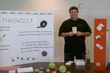
West Florida Components was recently invited to participate in a science experiments fair held in conjunction with the USF Education Department.

Each business staffed a booth where elementary school aged kids along with their families could conduct science experiments. The community event was an opportunity for families to enjoy and see the benefits of science in a fun atmosphere. The West Florida Components station was one of about 18 stations at which participants could interact and have fun with science. The event met a significant need identified at the national, state and local levels which is to increase the scientific literacy of students as a way to improve the local, state and global competitive status of our communities and our country.

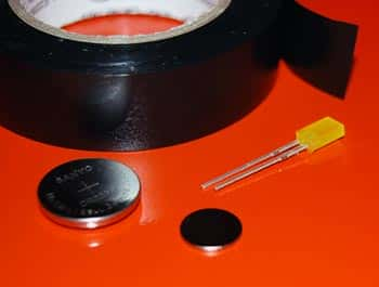
The staff from West Florida Components made LED Throwies with the fair attendees. Each family member was given an LED, a 3V battery, a magnet and some tape to put their LED Throwie together. Once the Throwies were assembled, they could toss their Throwie at a metal board to earn points. The families learned the science behind the Throwie and were given additional LEDS to take home to so they could rebuild their throwies and experiment further.

If you’d like the instructions to make the LED Throwies, you can visit our web site where we give full instructions with pictures.

Make a 9V headlamp head flashlight

Here’s an easy project that simple enough for electronic beginners, plus the supplies required are probably laying around your house or workshop.

Could you buy the same thing for just a few dollars more? Sure you could, but you’d miss out on the satisfaction of assembling this project all by yourself.

Here’s what you need:
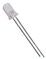
2 high intensity white LEDS (you can use other colors if desired)
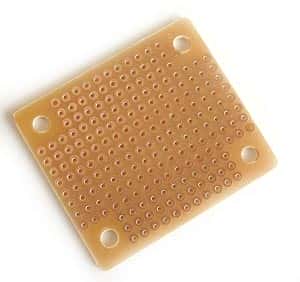
small perf board
2 470 ohm resistors
toggle switch or slide switch
9V battery snap
9V battery
small project box (you can use an Altoid tin)
electrical wire (about 2′ total)
soldering iron
solder
hot glue
electrical tape

For full assembly instructions, you can view the pages here:
http://www.instructables.com/id/9-Volt-Headlamp/