Author Archives: Andi

New Mystery Part: SCR5162-005 by Motorola

Sometimes we come across some new parts and there is no accompanying information. We search high and low for a data sheet but occasionally we are not successful.

One such part is the Motorola SCR5162-005. So far we know (think?) it’s a triac. But that’s all we got.

Do you know what it is? Do you have any specs for it? Let us know what you know and if we can verify the information, we’ll send you a $5.00 gift card to shop on our web site which is the best online store for electronic components.

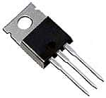
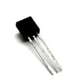
BUZ11 – a Popular Power MOSFET

BUZ11

BUZ11

The BUZ11 is an N-Channel enhancement mode silicon gate power field effect transistor designed for applications such as switching regulators, switching converters, motor drivers, relay drivers, and drivers for high power bipolar switchng transistors requiring high speed and low gate drive power. The BUZ11 is also used for DC-DC and DC-AC converters and in the automotive environment for injection, ABS, airbags, lampdrivers and more.

It features:

  • 33A 50V
  • Nanosecond Switching Speed
  • Linear Transfer Characteristics
  • High Input Impedance

The BUZ11 is in a TO220 package.

If you are looking at the BUZ11 with the drain (flange) at the top, the left pin is the GATE, the middle is the DRAIN, and the right lead is the SOURCE.

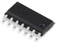
Low Power Quad Op Amps – LM324AD of the LM324 Series

The LM324 series consists of four independent,
high-gain, internally frequency-compensated operational amplifiers
designed specifically to operate from a single power supply over a
wide range of voltages.

LM324AD

LM324AD

In the linear mode, the input common-mode voltage range includes
ground and the output voltage can also swing to ground, even
though operated from only a single power supply voltage.
The unity gain crossover frequency and the input bias current are
temperature-compensated.

The LM324 is available in 3 packages: DIP 14, SO14 and TSSOP14.

He’s at it again! New Vacuum Tube Amplifier from Steve

Wow! Congratulations to our customer, Steve White, on his recent interview with the The Peterborough Examiner where Steve talked about his made-from-scratch vacuum tube amplifiers.

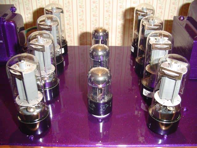
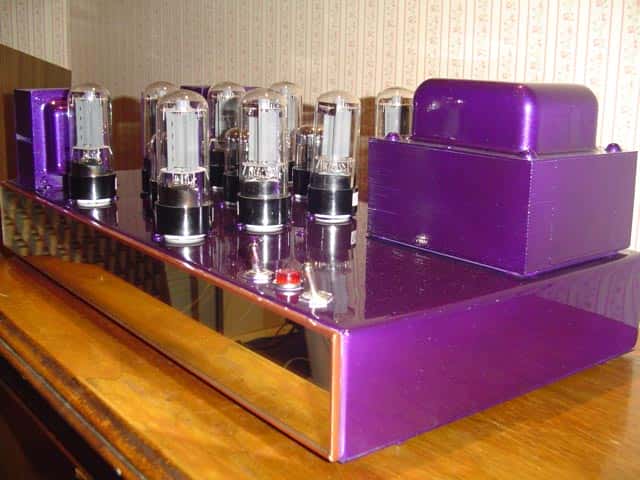
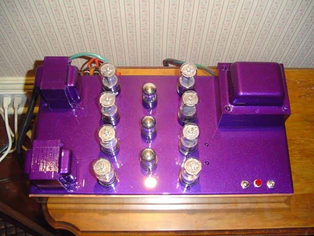
Steve sent some pictures of his latest project. He says it’s the biggest and most powerful amp that he’s made to date.

Here a new one. This is the biggest and most powerful amp I’ve made
yet! It’s a Push-Pull-Parallel 6L6 putting out a conservative 80 watts
per channel. I think I’ll keep this one for a while….
It has 8 of your 470 uf 400 volt electrolytic capacitors in it and one
of those small mylar coupling caps also.

Take a look for yourself…..

As always, great work, Steve.

7 Segment Displays

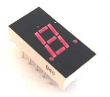
7 Segment LEDs or 7 segment displays are a type of electronic display devices used for displaying decimal numbers, in place of the more complicated dot matrix displays. 7 segment LEDs are used in a number of applications such as electronic meters, digital clocks and other such electronic devices.

7 Segment Display

7 Segment Display

As the name suggests, these electronic components are made up from 7 segments that are used for displaying each of the numerals from 0 to 9. The segments are arranged in a rectangle pattern with two vertical segments placed on each side, and a horizontal segment placed on top and bottom. In addition, another segment is placed bisecting the rectangle horizontally. This way, the figure obtained is of the number ‘8’. The segments are identified by lower case letters “a” to “g”, that begin with “a” on the top and going clockwise, with the center segment being “g”.

In some 7 segment LEDs, an additional segment is used to denote a decimal point and is referred to as DP. In some LEDs an extra triangle is also included to turn this decimal point in to a comma, which improves the readability of larger numbers.

Most of the 7 segment displays are slanted to make the numbers look like they were written in italics. This allows for one digit to be placed upside down along with another digit, such that the two decimal points appear like a colon between the digits. This arrangement of these electronic components is widely used in digital clock displays.

Meet the Amazing Alessandro Volta

Alessandro Volta was a renowned Italian physicist who is very popular for his work in the field of electricity. He was the first person to introduce the concept of an electric battery which was capable of producing a steady electrical stream.

Napoleon gave Alessandro Volta the title of count in appreciation for his work. Later, in honor of the great Alessandro Volta, the unit of potential difference or electromotive force was named Volt. In addition, the phenomenon of conversion of light energy to electrical energy is also named Photo Voltaic after Alessandro Volta.

How Do You Store Your Electronic Components?

Storing and retrieving a large number of electronic components like capacitors, resistors, LEDs, transistors, diodes, ICs etc. can be a daunting task not only because they are tiny but also because extreme temperature and humidity can deteriorate their performance. They also need careful handling as they are fragile and the tips can break easily.

In addition, electronic components need to be protected against static electricity.

To keep static electricity from damaging your sensitive electronic components, we recommend that you use sheets of anti-static foam. These foam sheets are easily cut to size to fit your storage containers.

A sheet of pink anti-static foam

A sheet of pink anti-static foam

There are a variety of container options to store electronic components safely. A range of molded ABS plastic boxes that can be side locked and stacked either vertically or horizontally are available. Each drawer has a number of compartments and can be labeled for easy identification. The various electronic components like resistors, capacitors etc need to be sorted and stored in these compartments in logical fashion. The drawers are easy to slide and can be pulled out / pushed in without much effort.

Ever wonder how the large electronic distributors store and retrieve their components? Automatic storage and retrieval systems make the job of storing and retrieving large numbers of electronic components easy and efficient. A typical construction has a vertical carousel in which a number of cameras are mounted on an endless chain activated by geared motors. The shelves are capable of rotating in either direction in a vertical plane. An electronic keypad facilitates calling the numbered carrier and bin / compartment. The system is equipped to store information about the location of code numbered electronic components in its memory. It can also be linked to a central computer for sharing of information for inventory control purposes. These automatic systems enable fast access of electronic components, instant stock update and save floor space, time, manpower and paper work involved in conventional storage systems.
AC vs DC – What is the Difference?

AC vs. DC

Electric current is the flow of electrons carrying electric charge. There are 2 types of electric current – direct (DC) and alternating (AC). In Direct Current the electron flow takes place only in one direction. A battery is a source of direct current. DC is widely used in many electronic circuits operating in low voltage levels.

In Alternating Current, both voltage and current alternate in direction back and forth following a sine wave pattern. The number of cycles per second, called the frequency, varies from 50 or 60 depending on the power system in a country. Alternating current is produced universally in power stations using AC generators. The AC theory is briefly described below.

A rotating coil in a magnetic field cuts the magnetic lines of force in two different directions during each half rotation in an AC generator. Thus the current produced travels alternately from left to right and then from right to left. When the coil is parallel to the magnetic lines of force, no current is generated. The alternating current so generated is collected by slip rings attached to the ends of the rotating coil and then transferred to an external circuit through metallic brushes.

Alternating current can be readily transmitted over long distances with minimum loss unlike DC. Any voltage drop along the way can be easily boosted using transformers. Also motors with high power can be designed using AC. Eddy current and radiation losses are the principal disadvantages of AC. 3 phase AC is generated in power stations, with each current out of phase by 120 deg to each other.

For a simple explanation about converters and inverters, visit this web page.

Five Easy Steps to Selecting the Right Switch

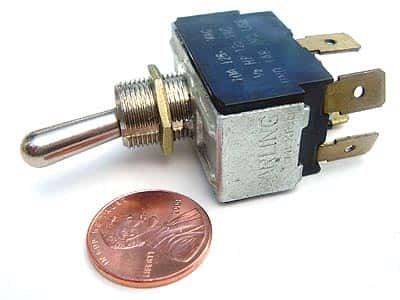
Although it is often one of the last components considered, selecting the correct switch is important when designing electronic equipment. Designers must be aware of the various options available in order to choose the most appropriate switch for any given application.
The procedure of selecting the correct switch can be summarized this way:

  • The requirements of the end user should be given consideration first
  • The engineering aspects like load, contact materials, terminal type, voltage, circuit type, mounting etc should be studied
  • Next the type of actuator should be decided
  • Standards like RoHS and similar government regulations must be complied with as well
  • Lastly, the switch chosen should be able to stand up to the rigors of the application. Environmental factors must be considered

When choosing a switch, you can ensure that the most appropriate switch is selected for the job if you take these factors into consideration.

What is Infrared?

What is Infrared?

The electromagnetic spectrum has waves of various wavelengths. Human eyes are capable to seeing the light that form a small part of electro magnetic spectrum. The waves with shorter wavelength as well are longer wavelengths than the visible spectrum are not visible. Infrared are waves that have longer wavelengths than the visible spectrum. The wavelengths corresponding to the Infrared waves are in between 750nm to 1mm.

Infrared waves cannot be seen but can be felt in the form of heat. Since the main source of infrared emissions is thermal source, so any thing that has temperature will emit Infrared emissions. Most of them are not noticed because they are not so strong. Higher is the temperature of the object, greater will be the Infrared emissions. Substances that seem cold such as a cube of ice also emit infrared.

Uses of Infrared:

  • Night vision: Infrared filters are utilized to filter 99 percent of the light of the visible spectrum and allow maximum infrared light to pass through them. This helps in viewing objects even in the dark based on their infrared emissions.
  • Thermo vision: Infrared emissions are utilized to find out the temperatures of distant objects. All celestial bodies emit strong Infrared emissions. These emissions are an easy way to study about the topography as well as climate of the celestial bodies.
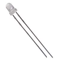
  • Communication: Infrared transmission is an easy way to transfer data for a short distance. Infrared finds its application in remote controls in which the Infrared LEDs are utilized to emit radiations that are focused over the Infrared acceptors. The Infrared LEDs also find their application in movement sensors such as optical mouse used in our desktop.
  • IR LEDS

    IR LEDS

  • Spectroscopy: Infrared waves find their applications in analysis of the molecules.
  • Satellite images: Infrared imaging is utilized by satellites to send in the details regarding the weather and geography of a place.