Author Archives: Andi

A New Vacuum Tube Amp – Flash Quattro!

Steve from Canada has just sent us some pictures of his latest creation. This one is fantastic!

Here’s what Steve had to say about it….

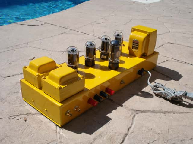
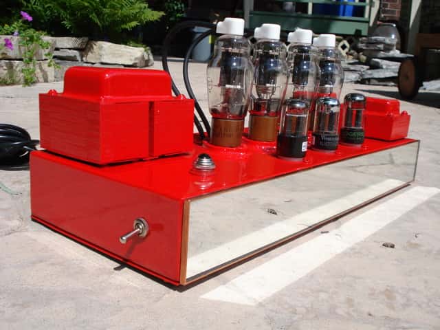
Hello everyone, meet Flash-Quattro.  That means “four flashes”.  I
chose the name because the 807 tube is very art deco and it made me
think of the 1930’s series ‘Flash Gordon’,   and there are four of them
hence the name,- simple!

This is the latest version of the ‘Book-shelf’ amp series, like the
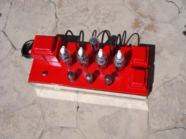
Caterpillar and Firecracker amps, this one is long and lean.

Now about the amp, it’s a push-pull 807 putting out 40 watts per channel or so,  in tetrode.  Rectification is with a 5R4, but you can choose to use 5U4
or 5Y3.  All supply the amp with more or less voltage and will change
the personality of the sound a bit.  I like the 5R4 so that’s why it’s
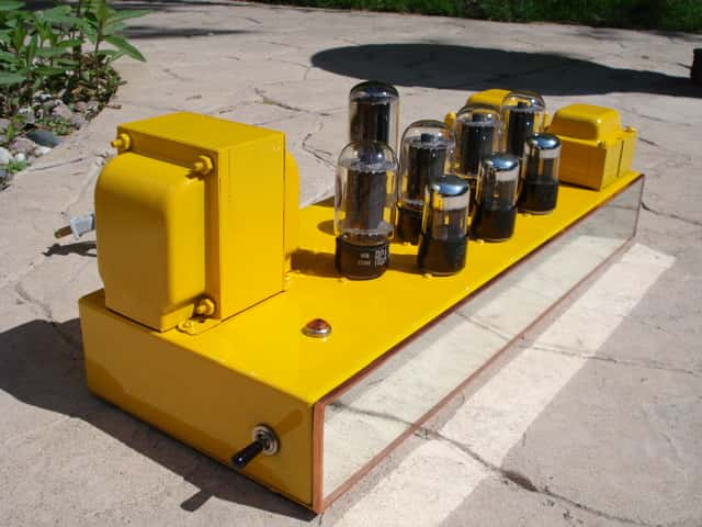
there.  Input tubes are a trio set of 6SN7GTB’s.

The output transformers are those nice Seeburg units that have Ultra-linear taps, but as I mentioned, I connected them in tetrode because I prefer the
sound of tetrode.  These outputs have impedance taps for 1,4,8,16 ohms.  A selector switch on the back of the amp allows you to switch
impedances ‘on-the-fly’ so you can choose and compare the taps you like
for what ever speakers you’re using at that time.  There is no problem
using the 4 ohm tap on an 8 ohm speaker, it how it sounds to you.

The power transformer is a Lowrey unit and a plate voltage of 373 vdc.
Classic green jewel light and side toggle On/Off switch.  Painted by my
good friend Joel Luttrell, and having his signature touch, a flawless
mirage of firecracker red (yes the same red as used in the
‘Fire-Cracker’ amp) and ice-pearl sparkles.  Apparently a fly decided
to do the back-stoke in the final coat of clear, so Joel had to pluck
out the fly, buff, and add more coats of clear.  Knowing Joel, there’s
probably 10 or more coats of clear here!
Take a look…..

vacuum tube amp


vacuum tube amp


vacuum tube amp


As always – thanks for sharing, Steve. We are amazed!

Opening Up and Tearing Down an IPOD Shuffle

Opening up and tearing down an IPOD Shuffle to see what’s inside…

The 3rd Generation of the IPOD Shuffle is a wonder of technology….1000 songs stored in an aluminum case smaller than a disposable lighter.

Did you ever wonder what electronic components make up the guts of an IPOD Shuffle?

You might be surprised at what goes into the circuitry of the IPOD Shuffle. In descending order by percentage of cost, the main components are:

logic, memory, metals, rechargeable materials, connectors, PCB, crystal, misc, capacitors, transistors, analog, diodes, magnetic, and plastics.

Here’s a partial breakdown by number of electronic components:

Capacitors – 65+
Resistors – 50+
Diodes – 4+

Pretty amazing what goes into equipment that measures only 45.2mm x 17.5mm x 7.8mm when fully assembled! This is possible because the components are extremely small surface mount components.

If you look at the cost breakdown by component family, it’s just as revealing. Naturally, the largest share is for memory in the form of IC’s. Over 70% (about $12.00 worth) is for logic and memory.

Available Methods of Marking Semiconductors

Semiconductor Markings – Available Methods

Traditionally, most components have two or three lines of identifying marks plus a company logo. Over time, the manufacturer codes have become more involved to incorporate a component’s identification plus the complete history of the process. Early on, it was the military applications that required very specific markings and identification processes. Current package markings are a by-product of those military requirements.

When a semiconductor is clearly identified, there is less room for error in the production process. Reducing errors when a component is in use for production saves time. There is also less product waste and the production process becomes more streamlined.

As the size of electronic components has decreased, the available space that manufacturers have to mark each piece has also decreased. The technology required to complete this task has become increasingly more complex.

The chief reason for the more complex codes stems from the demands of the end users. They need to have complete traceability of the product; from the history of the production cycle including the date and location of manufacture to the exact lot code. Possession of this information is critical to the end user in the event of a recall or defective components.

There are four primary methods to marking components in current use. Use of the various methods depend on the size, the type and the environment of the component production.

The methods are:
-Ink marking
-Electrolytic marking
-Pad printing
-Laser marking

In ink marking, inkjet printers are used. The technology is called ‘drop-on-demand’ which means that the flow of ink is controlled to create a pattern of ink droplets to form an image marking.

Electrolytic marking employs low voltage electric current with a stencil. The top layer of the package is etched by electricity flowing from the marking head, assisted by an electrolyte chemical. The process takes approximately 2-3 seconds to complete.

Pad printing is the most traditional of all the processes. A steel plate is etched with the image of the imprint. The ink is transferred to the plate which then is applied with pressure to the surface of the electronic component.

Laser marking is the most recent development in the marking process. It provides the greatest flexibility in the size, timing and complexity of the markings. The laser process is also the fastest method to mark electronic components; it is not uncommon for this process to print up to 300 characters per second. An additional benefit of using laser printing is the ability to produce a clean mark on many irregular surfaces.

No matter which method has been used to mark the semiconductors you use, you can be sure that much thought has been put into the decision.

How To Clean Potentiometers On Your Audio Equipment

How to Clean the Potentiometers on Your Audio Equipment

If you have a dirty potentiometer, you probably will find out about it from the scratchy sounds your equipment will make when you adjust the volume control.

Here’s a simple and safe method to rid yourself of that noise:

-Unplug your equipment
-Remove the cover from the knob
-Carefully use contact spray on the shaft of the potentiometer
-Replace the knob
-Plug your equipment back in and turn it on
-Rotate the knob from one end of the range to the other.

Did that work? It should have – but if you still hear the scratchy noise, you can move onto this step:

-After unplugging the equipment again, remove the potentiometer from the housing and use the contact spray at the base. Before you put it back into the housing, rotate the shaft to be sure that it’s moving cleanly.

If you still hear noise, it might be time to replace the potentiometer. Before you cut the wires, it is recommended that you snap a couple of pictures of the previous installation including all wires leading to the potentiometer. This will assist you greatly when it’s time to connect the new pot.

Once you obtain the correct pot to install, you will need to use solder and a soldering gun to reconnect the wire leads from the potentiometer to the equipment.

Hopefully it won’t be necessary to replace the potentiometer. Most often, a spray is all it takes to rid yourself of the noisy potentiometer.

Solar Panels for Boats

Solar panels can easily be installed and utilized on boats for power. There is very little maintenance required to keep them in working condition and if properly installed, the solar panels should last 10 years or more.

The first decision is what kind of solar panels to buy. The most efficient option are mono-crystalline solar panels. Not only are they efficient, they are the most widely available. You might also consider using poly-crystalline panels which are slightly less efficient as the mono-crystalline type. If you have concerns about shade, you can buy the thin film solar panels.

Your next decision is where to install them on your boat. It is recommended that you install them high and aft on your boat, and in direct sunlight. One suggestion would be to install them maybe over the cabin or above the davits. The goal is to avoid installing them where the shadows might affect their performance. If shadows are an issue, consider installing them on a rail along the stern or over the bimini.

If your solar panels are shadowed, even just one complete row of cells, you will not be generating any power. The solution would be to either move the solar panels to a location that is not shadowed or to use a shade resistant amorphous solar panel.

Keep your solar panels operating at their maximum efficiency by wiping off any residue laying on the surface of the panel. Solar panels generally require little maintenance and are able to withstand the outdoors, so think about how you might be able to use them to power your boat.

Custom Tube Amps Are the Best Sounding

Steve White from Canada has been busy building more custom tube amps.

Here’s a beauty that Steve painted ‘caterpillar yellow’


Here’s what Steve had to say about his latest project:

So, here’s the new Caterpillar tube amp. Geared to appeal to the heavy
machinery crowd. Painted the classic Caterpillar yellow with brilliant
white sparkles in the paint. Painted by Joel my painter. This amp is
40 watts per channel. 355vdc on the plates of the 6L6 tubes. Selector
switch to go from 4-8-16 ohm speakers, a nice heavy duty on/off switch
on the side, and a authentic classic jewel pilot light.

Just beautiful! Check out more of Steve’s creations here: Vacuum Tube Amplifiers

Grounding Wire in Your Solar Energy System

As they become increasingly popular among both homeowners and businesses, solar energy systems are helping to create a world full with the possibilities of clean, renewable energy.

The efficiency, affordability, and environmentally friendliness of solar panels and accessories are a far cry from the costly, wasteful, and polluting methods of power generation traditionally used to secure energy for the booming population around the world. But this innovative technology is not without its perils, the foremost of which is the danger of electrical shock and related fires. This serious risk is easily mitigated by the practice of grounding a solar energy system. It’s easy, fast, and inexpensive, and in many places, including the United States, it’s required by NEC laws for most systems and applications.

To “ground” a given electrical system means that it is connected to the earth, which provides a shield between the power conductors and a person or separate object. The practice of grounding solar energy systems is important for a variety of reasons. Most modern systems are installed on rooftops and other similarly elevated spaces to achieve maximum sunlight exposure. While this positioning is optimal for efficient solar panel usage, it also exposes systems to electric wiring, antennae and satellite equipment, and telephone and cable systems which can be prone to breakage and hanging, especially in areas that experience turbulent weather. The common positioning also exposes systems to objects such as tree limbs and debris.

These objects, if brought into contact with a non-grounded solar energy system, can contribute to shortages and create a fire risk too dangerous to ignore. In addition to these accidents, non-grounded systems can cause electric shock when touched by humans and animals, especially those systems which carry a high voltage or are in their veteran years of use.

The process of grounding a solar energy system is a basic one; a “ground” or rod is driven into the earth, preferably at a depth of at least a foot or two, and a proper grounding wire is tied to it. This wire is then attached to the solar energy system, completing the barrier. It is important to note that the grounding set ups of AC and DC systems must absolutely be kept separate, and that excess grounding wire can become a hazard all its own.

With the proper length grounding wire, a simple rod, and a careful attention to detail, you can render your solar panel system both safe and reliable while complying with important regulations.

The post above is offered as an opinion. If you are installing a solar energy system, please consult an expert for exact instructions to protect yourself and your property. West Florida Components accepts no liability for you, your property or your solar system.

Types of Diodes

Diodes are an important part of today’s electronic components and are widely used for a number of applications. Accordingly, a large number of different types of diodes have been created to cater to their wide array of uses. The more popular types of diodes are described below.

Schottky Diodes: These diodes are made from a semiconductor to metal contact instead of semiconductor-semiconductor junction. This gives them a lower forward drop voltage as compared to pn junction diodes. They have a faster reverse recovery time and high switching speeds due to the low junction capacitance. They are used in voltage clamping applications and as low loss rectifiers.

LEDs (Light Emitting Diodes): These electronic components are formed from direct band gap semiconductors like gallium arsenide, and as the carriers cross the junction and recombine with the majority carriers, they emit photons. Infrared to ultraviolet wavelengths can be obtained depending upon the material used for making the LEDs. They are often used in signaling operations.

Varactor Diodes: These diodes are used as voltage controlled capacitors and have important applications in frequency locked loop and phase locked loops used in tuning circuits.

Zener Diodes: Zener diodes permit current to flow in the forward direction as in a normal diode, but where it differs is that it also allows current to flow in the reverse direction when the voltage exceeds the breakdown voltage also referred to as Zener voltage or the Zener knee voltage. It can be used as a precision voltage reference.

Avalanche diodes: These diodes are also used for conducting in the reverse direction once the reverse bias voltage increases the breakdown voltage. The reverse bias causes a wave of ionization, like an avalanche, and leads to a large current.

Tunnel diodes: These diodes have a negative resistance region of operation that is caused due to quantum tunneling. This allows for amplification of signals. These diodes offer most resistance to nuclear radiation.

Gunn Diodes: These diodes are similar to tunnel diodes except that they are made of different materials, like InP, GaAs, and exhibit negative differential resistance.

If you are just beginning to work with diodes, you might want to purchase a small amount of each type listed above. A good source for all diodes and other electronic components is West Florida Components.

Rotary Switches: Construction and Use

A rotary switch is a kind of switch that has a rotating shaft attached to a terminal. That terminal is able to make or break a connection to one (or more) other terminals. Rotary switches may feature different switch positions that can be set by rotating the switch spindle in one or another direction. Some common examples where a rotary switch might be used is in a multi-speed fan or as a band selector on multi-band radios. Until the early 1970’s, rotary switches were used as channel selectors on TV receivers.

In general, rotary switches can be found where ever there is a need to control a large number of circuits covering a range of currents, voltages and power requirements. Currently, you will find rotary switches in these applications:

  1. medical equipment
  2. computers
  3. industrial controls
  4. instrumentation
  5. communications equipment
  6. aircraft equipment

The construction and design of a rotary switch is centered around the center rotor. The rotor has a contact arm that projects out from its surface. Around the rotor are an array of terminals. These serve as the contact for the arm, or spoke. Since the switch has multiple layers, each layer permits the use of an additional pole. There is also a detent mechanism which will click into place as the switch is turned from one active position to another. The contact / sensor system and detent mechanism determine the number of possible switching combinations.

Grayhill Rotary Switch

Grayhill Rotary Switch


Above is an example of a Grayhill military rotary switch. You can see it has 5 decks. Each deck has 1 pole. Each pole has 9 positions.

This is an example of a 16 position rotary switch assembly 1-435304-1. This rotary switch assembly has a bar handle. It is a single pole but has 16 positions.

All About Self-Adhesive Rubber Feet


Square Rubber Bumpers

Square Rubber Bumpers

Self-adhesive rubber feet, also known as bumpers or bumpons, are a versatile product that can be used in many different ways around the house and workshop.The self-adhesive glue will stick to most surfaces including glass, wood, metals and plastics.

In the home, you can use rubber feet as dampers to cushion the closing action of cabinet doors or drawers in your kitchen, bathrooms and laundry rooms. The rubber bumpers will protect your expensive cabinet doors and drawers from hitting the frame of the cabinets and maintain the integrity of the wood by preventing vibrations when door meets the cabinet. Another way to use rubber bumpers in the kitchen is to attach them to the bottom of cutting boards to prevent the board from skidding, Many small kitchen appliances have rubber feet on the bottom to keep them from sliding.

There are other places in the home that rubber bumpons can be used. Put them on the underside of hanging pictures to help them grip the wall and help the frames stay in place without damaging the walls or the artwork.They can be adhered to speakers to protect the floor from scuffing and keep vibrations to a minimum. Your electronic equipment needs air to circulate between the cases. Using tall rubber feet as spacers will separate the equipment and allow air to circulate.

In the home office, rubber feet can be used on keyboards to grip the surface of the desk. Computers and laptops have rubber feet on the bottom which keeps them from sliding.If one of them is lost, your computer will be unbalanced and hard to use.

Rubber feet are often used with electronics projects. Once common place is on project boxes and pc cases. You will also find them on circuit boards.

In addition, rubber bumpers can be found in automotive applications, woodworking projects, glass projects such as coasters and stained glass window hangings.

Rubber bumpons are generally sold in three shapes: cylindrical, hemispherical and square.

Use the flat (cylindrical) rubber feet when you need increased load capacity. The hemispherical feet are most often used when increased sound dampening is required. Hemispherical rubber bumpers are favored for increased energy absorption.

The thin, low profile bumpers are great for increased load capacity. Their flat, wide surface helps absorb weight evenly. If you require air circulation, the taller, high profile rubber bumpons would be the best feet for the job.

Clear and black self-adhesive rubber feet are the most widely requested colors but many of the feet are also produced in gray.

Large Self-Adhesive Rubber Feet

Large Self-Adhesive Rubber Feet

Keep a supply of self-adhesive rubber feet in different shapes, sizes and colors around the house for the next time you need to use one of these versatile products.They are an inexpensive solution for many projects.