Author Archives: Andi

Connector Terms and Glossary

Are you a connector newbie? Below is a collection of terms relating to connectors with their corresponding definitions.

Attenuation – Decrease in power due to resistance or mismatch in transmission line.
Back Mounted – When applied to a coaxial connector it is that connector mounted from the rear of a panel with the fixing nut on the outside.
Bandwidth – Distance between two frequencies over which a RF or microwave device is intended to work.
Between Series Adaptor – An adaptor used to connect two different generic types of connector.
BNC – Bayonet Nut Connector.
Braid – A weave of metal strands used as an electrical shield for an insulated conductor or group of conductors.

Connector

Connector


Bulkhead Mount – The type of connector fitted to a chassis using a single cut-out hole.
Cable Retention – The mechanism that joins the connector to the cable.
Cable Retention Force – The axial force which a connector / cable join can withstand.
Captive – A component such as a contact which is held firmly in position.
Characteristic Impedance – That impedance at which the transmission line is intended to work. A change from the characteristic impedance along its length will cause mismatch and loss of power.
Clamp – The holding of a cable by use of a screw thread action.
Closed Entry Contact – A female contact which is designed to prevent insertion of a contact larger than that specified.
Coaxial Cable – A transmission line where the one conductor is concentric inside another, often abbreviated to “coax”.
Coaxial Termination – A resistive element used to end a coaxial line in its characteristic impedance.
Coaxial Terminator – A device for terminating coaxial cable to a PCB or bulkhead mount (a mechanical device and should not be confused with coaxial termination)
Conhex – Tradename covering SMB and SMC, both in 50 Ohm and 75 Ohm impedance (discontinued)
Connector Durability – The number of times a connector can be physically mated and still maintain its specified performance.
Contact Resistance – The measurement of the DC electrical resistance between a pair of mated contacts. Usually specified as being measured after a given number of mating cycles.
Corona – A discharge of electricity caused by the ionisation of the air around a conductor just prior to total breakdown or flashover.
Crimp – The action of distorting a metal tube to give intimate contact with a conductor; a good crimp should be gas tight and not be impacted by environmental change.
Crimp Dies – The tool inserts which determine the shape of the distortion to create a consistently good crimp.
Crimp Tool – The tool which holds crimp dies to apply the necessary force.
Cross Talk – The amount of signal which may be transferred from one signal carrying line to an adjacent line.
Cut Off Frequency – The frequency at which the loss exceeds a predetermined level.
Decibel (dB) – A unit of measurement of RF power loss.
Dielectric – The insulating medium which holds the center conductor concentric within the connector or cable.
Dielectric Constant – The electrical value of dielectric which determines the impedance in cables or connectors with constant diameters.
Dielectric Withstanding Voltage – The maximum voltage that a dielectric material can withstand without failure.
Direct Solder – A common method of terminating connectors to semi-rigid cable by soldering the cable jacket to the connector.
Discontinuity – A dramatic change in characteristic impedance which gives rise to a reflected wave.
Dissipation – The unused or lost energy in a system e.g. heat.
Distortion – An unwanted change in a signal wave form.
Dummy Load – A device connected to the end of a transmission line to absorb transmitted power and prevent reflected energy.
Dust Cap – A mechanical device attached to the mating face of an unmated connector to prevent ingress of contaminants and provide protection against mechanical damage.
Electromagnetic Compatibility (EMC) – The ability of a device to operate within its intended environment without being effected by or generating electromagnetic interference (EMI).
Engagement and Separation Forces – The forces required to mate and unmate a pair of connectors. The forces are usually specified as a max & min for each action.
Environmentally Sealed – A connector that is provided with seals or other devices to prevent ingress of dust, moisture or other contaminants while mated which might impair performance.
Flexible Cable – A coaxial cable where the outer conductor is flexible (usually braided).
Gigahertz (GHz) – A measure of frequency representing 1 billion Hertz (cycles per second).
Impedance – See ‘Characteristic Impedance’
In-Series Adaptor – An adaptor which enables the connection of two connectors of the same generic type.
Insertion Loss – The loss of power due to a particular component in a transmission line (e.g. cable).
Insulation Resistance – The electrical resistance between two conductors separated by an insulating medium.
Intermodulation – The mixing of two or more frequencies which are not intended to mix.
Interface – The two surfaces of a connector which come into intimate contact when the two halves are mated.
Inter-series Adaptor – See ‘Between Series Adaptor’
Isolation – The measure of interaction between two or more transmission lines.
Jack – One half of a mating pair of connectors. The jack interface normally goes inside the plug interface.
Mean Power – The mean value of the rate at which energy is transmitted from one place to another.
Micro Strip – A transmission line consisting of a flat conductor on a dielectric above a single ground plane. (the ground plane is frequently a metalized face of the dielectric).
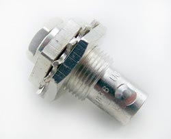
UG909B/U Female Bulkhead Clamp Kings Connector

UG909B/U Female Bulkhead Clamp Kings Connector

Microwave – Very short electromagnetic waves. Frequency range above 1 GHz.
MIL-C-39012 – The generic specification covering USA Military coaxial connectors.
MIL-C-17 – The generic MIL spec covering coaxial cables.
Mismatch – The condition in which the impedance of the source and load are not the = same. This reduces power transfer and causes reflections.
Mounting Plan – The design of the PCB or panel cut-out used to mount the connector. N Connector – This was the first true microwave connector capable of working to 18GHz, initially designed for test applications.
Nanohex – Trade name covering SSMB & SSMC (discontinued)
Noise – An external electromagnetic signal which interferes with the desired signal.
Non-captive – A component such as a contact which does not have a retention feature.
Passivation – This is a surface treatment applied primarily to stainless steel. The process removes contaminating iron particles and produces a passive surface.
Peak Power – Is the maximum power which may be handled by a connector or cable.
Plug – One half of a mating pair of connectors. The plug interface normally goes outside the jack interface.
POSNS – Abbreviation for “positions”.
PTFE – Abbreviation of polytetrafluorethylene. This is the most commonly used dielectric (insulator) used in professional coaxial connectors.
QPL – Qualified Parts List. Parts approved to MIL-C-390 12 specification.
Receptacle – A term used to describe a connector assembly usually bulkhead or PCB mounted.
Return Loss – A reason for loosing RF energy due to signals being reflected due to a mismatch in a transmission line.
RF Leakage – The RF power lost from a transmission line or device. Measured in dB.
RG – The traditional prefix for MIL spec coaxial cables.
Screw-on – The mating action of connectors which are joined using a screw thread (e.g. SMC)
Sealflex2â„¢ – Cannon trade name for a flexible microwave cable assembly which has a performance similar to semi-rigid cable.
Semi-rigid Cable – A coaxial cable where the outer conductor is a solid metal tube.
Skin Effect – The tendency of alternating currents to flow near to the surface of a conductor; this increases resistance and becomes more marked the higher the frequency.
SMD – Sometimes used as an abbreviation for slide-on variants of SMB. This is a misnomer, the more common use is for Surface Mount Device.
Snap-on – A term used to describe the mating action of SMB and SSMB connectors.
Solderless SMA – An SMA connector that can be connected to semi-rigid cable by compressing the inner body rather than by soldering (sometimes referred to as semi-rigid ‘crimp’ connectors).
Stripline – A method of building a microwave circuit. The circuitry is sandwiched between 2 ground planes. Sometimes referred to as Tri-plate.
Teflonâ„¢ – DuPont tradename for PTFE.
Tensile Strength – The greatest force a device can withstand without tearing or pulling apart. This is frequently the method of determining the effectiveness of a crimp.
TNC – Thread Nut Connector same size as BNC; the only obvious difference is the coupling nut.
Tri-plate – See Stripline.
UG Symbol – Used to indicate a connector made to US government spec.
Voltage Standing Wave Ratio (VSWR) – A way of expressing the resultant loss of power as a result of signal reflections due to discontinuity.

The Titan – Newest (and biggest) Vacuum Tube Amp from Steve

Just in from our friend Steve W. in Canada (who constructs the most amazing vacuum tube amplifiers)…

The best way to describe this next amplifier is it’s a Titan. It has to be the biggest, baddest, heaviest and most powerful amplifier I’ve made to date! Weighing in at just under 60 lbs. this push-pull-parallel EL-34 / 6L6 is conservatively rated at 110 watts per channel using EL-34 tubes. Capable of driving 4 or 8 ohm speakers via a switch on the back panel, this amp is a tube roller’s dream.

Simply by plugging in which rectifier tubes you want to use, be it a pair of 5Y3’s, 5R4’s, 5U4’s or even 5AR4’s you can match the correct plate voltage with what ever power tubes you choose, be it a set of 6V6’s, 6L6’s, 5881’s Kt-66’s, Kt-77’s, EL-34’s, or even 7591’s.

You also have the choice of running the amp in push-pull instead of push-pull-parallel simply by not installing the front four power tubes and switching off one of the two rectifier tubes via a switch located on the right hand side of the chassis. The signal and phase-inverter pre amp tubes used are my favourite large dual triodes 6SN7’s.

Now, about the transformers, seeing that this amplifier has to drive thirteen tubes, I thought it only made sense to use a separate filament power transformer. The transformer right next to the larger power transformer is the 20 amp filament transformer. By doing this, I’ve removed the heater load off of the main power transformer which now only has to supply the high voltages the amp needs.

Along with a hefty octet of 470 mfd 400 volt capacitors bought from West Florida Components, there is more than enough capacitance to keep this amp in the black during those high current moments when the music demands it.

By sharing the load this way, the main power transformer will not be taxed nearly as much. The output transformers are massive Hammonds that can easily handle the wattage this amp delivers.

You will notice a volume control knob located right smack in the middle of the mirror in front of the amp that’s surrounded in pure copper foil, and that is because this is a fully integrated power amp with a line stage pre amplifier built into it. That means you do not need to buy a separate pre amplifier. You only need to plug in your CD player, satellite, MP3, I-pod, or what ever type of line stage device you like to use, directly into the amplifier.

There are two benefits to an integrated amp, one, you don’t have to go out and spend money on a separate pre amp, and two, you are amplifying completely with tubes throughout the whole amplifying process from pre amp to power amp, and that makes it sound better, way better!

Once again – amazing job, Steve! Thanks for sharing this with our readers.

Tantalum Capacitor Industry Needs New Resources

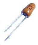
Tantalum Capacitor

Tantalum Capacitor

As the demand for tantalum has recorded 5% growth every year, the supply of tantalite has decreased setting up the electronic components industry with a possible shortage.

Tantalite, which is the key component of tantalum used to make tantalum capacitors, is mined primarily in three countries: Australia, Mozambique and Canada. Companies in those countries reduced or suspended production as the economy tanked in 2008 and consumer spending fell.

Recently, most production of tantalum has been taking place in Brazil and Africa but with the previous production facilities not producing the tantalum, a shortage through 2012 is possible.

What does that mean to consumers and companies that need tantalum capacitors?

Increased demand will push prices higher on current stock….and if current supplies are depleted, a shortage like the one that occurred in 2000 may occur pushing up prices even further.

Tantalum capacitors have grown in popularity for many reasons. To start with, tantalum capacitors have a larger volumetric efficiency when compared  to other types of capacitors. To illustrate this point, a 10uF tantalum can be used in place of a 100uF aluminum capacitor.

In addition, tantalum capacitors are able to be inserted on circuit boards easily. When you couple this with the tantalum capacitor’s greater  power dissipation characteristics when looking at other capacitors in this size range, tantalum capacitors  can be inserted in small spaces. This makes them good candidates for tightly designed boards. You will often find tantalum capacitors used in laptops, computers, cellular phones, auto circuits and other similarly sized electronic devices.

Another outstanding characteristic of tantalum capacitors is their nearly unrivaled life span. The shelf life of tantalum capacitors is unparalleled when looking at other capacitor types such as those made from electrolytic material since the performance qualities stay intact over time and they should not lose capacitance like many other popular capacitors.

A Console Stereo: Steve’s Legacy Project

We continue to be amazed at the work that our friend and customer from Canada, Steve White, does.

Luckily for us, Steve graciously shares his talents by allowing us to post pictures of his recent projects.

Here’s what Steve said about his console stereo:

If I were to ever to have a legacy, this project would have to be it! Ever since I was 5 years old I’ve wanted a console stereo. 38 years later and I finally have one.

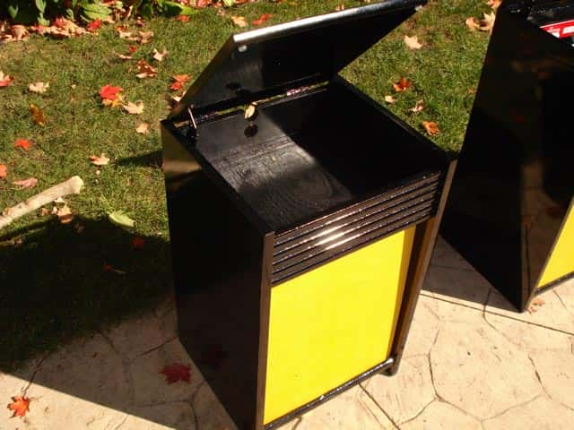
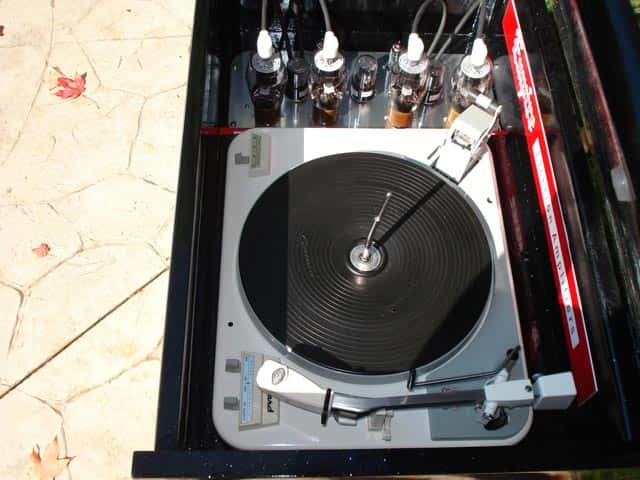
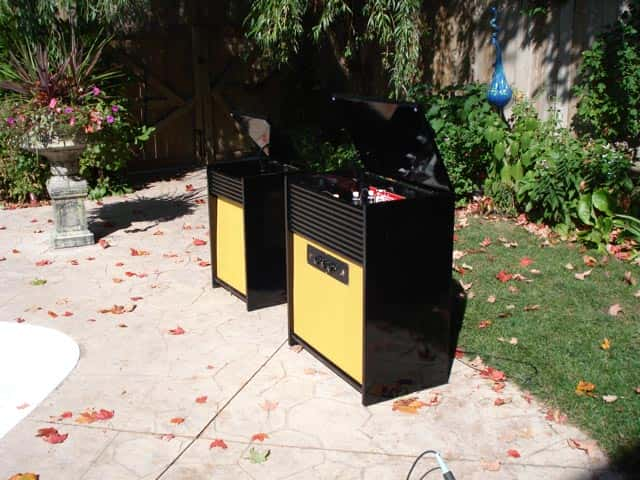
I took 2 old Magnavox cabinets that were originally the same size (both same as the large one) and added to the larger one to accommodate the turntable, and shrunk the other to be a satellite speaker to allow you place it where ever you wanted to in your room to give you the true stereo separation.

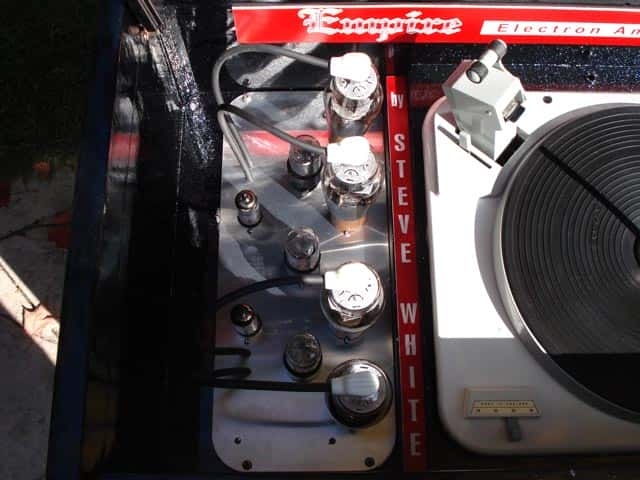
I then painted the cabinets Jet black with ice-pearl sparkles. I wanted the tube amplifier to be displayed unlike in older consoles, right next to the turntable, because to me the amp is art! I then completely restored this 1962 Garrard turntable that was reclaimed from an old console, and put the whole thing together.

Here is the result…. Sounds really nice too!

Job well done, Steve!

Round, Cylindrical or Hemispherical: Rubber Feet Dilemma Solved

You need some rubber feet but don’t know what shape to buy? Look no further. Here is the information you need.

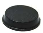
Do you want the top of the self-adhesive rubber feet to have a flat surface? You should choose a cylindrical rubber foot. Cylindrical rubber feet are basically shaped like a coin….flat top, and flat bottom.

They are perfect for situations where you need to use them between two flat surfaces. Some suggested uses are for the back of pictures and art hung on the wall; for kitchen and bathroom cabinets to cushion the close; and craft projects like coasters and stained glass projects. We’ve even seen them used to place sheets of glass on tabletops to separate the glass from the surface underneath. Cylindrical rubber feet are available in both clear and black.

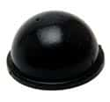
Do you want the self-adhesive rubber bumpers to be rounded? Then you need to purchase hemispherical rubber feet. Think of a ball cut into half – rounded on one side; flat where the adhesive attaches to the surface.

Hemispherical rubber feet are perfect for separating electronics equipment to help air circulate between two boxes. They are also ideal for applying to surfaces when you need a little bit of a grip on the surface underneath.

Here’s a unusual use for a hemispherical rubber foot: Apply with the adhesive side down on a bookshelf or display cabinet to hold propped up items in place. Clear rubber feet work perfectly on glass shelves! Like cylindrical feet, hemispherical rubber bumpers are available in clear or black.

Solar Energy in China: Here Comes the Sun

Growing demand for renewable energy sources has skyrocketed all over the world, but no where is this more evident than in China.

Take a look at the city of Rizhao where miles of dark tubing cover the roofs of apartment buildings and private homes. The reason? Using solar powered hot water heaters is mandatory in Rizhao. In fact, due to requirements such as this one, China has become the largest producer (and consumer of) solar hot-water heaters. Rizhao’s commitment to solar energy is deep: it has pledged to become the very first city in China to become carbon-neutral.

The good news for all of us is that the surge in solar panel requirements has created more supply, and thus lower pricing for all of us. The lower prices help make solar energy more affordable even here in the US.

As new panels are shipped to us, we will be passing on the new lowered prices to our customers. West Florida Components has just lowered our prices on all new solar panels by an average of 16%. Good news for all of us!

Rubber Feet – How to Apply Self-Adhesive Rubber Bumpers

Many customers have asked about the best way to apply self-adhesive rubber feet to surfaces so that they are properly applied…and stay on the intended surfaces.

Here are the recommended application instructions:

    • Clean the surface where you will be applying the rubber feet. It should be dry and free of debris, oils and solvents. In addition, the ideal surface for rubber feet application is smooth and non-porous. You can use a mild solvent such as isopropyl alcohol to remove dirt or grease.
    • Grasp the rubber bumper on the sides without touching the adhesive.
    • Press the rubber bumper firmly into place on the application surface. The rubber foot can not be repositioned without effecting the adhesive.
    • For best results, allow 24 hours before exposing the rubber feet to heavy force or weight. This allows the adhesive on the rubber feet enough time to ‘cure’.

Besides following the above instructions when applying the rubber feet, it is important to keep the rubber feet (both storage and use) at a temperature that is between 70° – 80°F (21° – 27°C).


Choosing Batteries for a Solar Energy System

When putting together a solar energy system, like any other project, having the proper parts and tools for the job is paramount to overall success. With quality components and a little bit of know how, you can design and install your very own solar energy system whether for dedicated appliance use or as a complete replacement for conventional electric energy. Choosing the right parts is a big step in the process, and once you’ve decided which type of solar panels to use and how many you’ll need, the next logical step is to find appropriate batteries.

The most important step in choosing batteries for your solar energy system is making sure you purchase a bank with corresponding voltage to the panel array you’ve designed. The voltage of individual battery units on the market is 2; depending on how many individual battery units come in the bank, the voltage of the unit itself will be 2, 4, 6, 8, and so on. Once you’ve established the correct voltage for your battery bank, you can browse the available types and models to arrive at the perfect unit for your system. There are four basic kinds of battery banks widely available for purchase: marine models, and “industrial strength” varieties which include flooded, gel, and AGM features.

The marine models, commonly used on boats and small vehicles such as golf carts, tend to be the least inexpensive, and may be an option for small solar projects or those requiring solar powering for a limited period of time. In the long run, however, purchasing an industrial battery bank will save money. Flooded battery types are an economical option, with a moderate price and a reasonable longevity. These types release gas while charging, and so are not suitable for indoor use. Gel batteries, while a little more expensive, do not release gas allowing for indoor use, and come with a slightly longer life expectancy. Finally, AGM batteries may cost more, but have numerous benefits, including the longest longevity available, lack of gas or other leakage, and superior efficiency.

Taking care to select the battery bank that’s right for your solar system and its application is an important part of the overall design process, and, if done carefully, can lead to many years of nearly maintenance-free energy enjoyment. Shop with quality in mind and give yourself the gift of peace of mind for years to come.

Schottky Diodes – What makes them so special?

Some of the most common questions we get are about Schottky diodes.

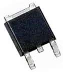
Schottky Diode

The simple definition of a Schottky diode is a diode with a very fast switching action as well as a lower forward voltage drop.

As the current flows through a diode, it experiences a slight voltage drop across the diode terminals. Normally, a diode has approximately 0.7-1.7V drops. A Schottky diode, however, will see a drop in voltage between 0.15-0.45V. The benefit of this lower drop? A much higher system efficiency.

The construction of a Schottky diode also effects the voltage drop and switching time. A Schottky diode has a metal semiconductor junction as the Schottky barrier rather than the traditional semiconductor to semiconductor junction seen in conventional diodes. It is this barrier that affects the voltage drop and the speed of the switching times.

Sometimes Schottky diodes are misspelled by adding an ‘e’ to the end: Schottkey. The correct spelling is Schottky which is the surname of the man that is credited with putting these electronic components in the history books.

RGB Tricolor Flashing LEDS – Exciting New Product!

West Florida Components has just started to carry an exciting new product – RGB Tricolor Flashing LEDS!

At first glance you might think “Why are they calling them both RGB AND Tricolor?” The reason is that each LED is actually 3 separate LEDS housed in one case.

They operated in a sequence: first one color is lit at a time, then two light up, then all three. The cycle is completed when all three LEDS have been lit slowly, then begin to flash. Max voltage is around 3V.

We were trying to think of some interesting uses for these LEDS. Certainly they’ll be fun to use around the holidays – in garland or in wreaths or other holiday projects. How about as a centerpiece? They would also be great for costumes and for jewelry making.

Here’s a challenge for our customers:

Use your imagination and find a great project to use these in. We’ll feature the best suggestions/projects in a video on our home page!