Author Archives: Andi

How Do You Measure Current Flowing In A Circuit?

Engineers have several methods of measuring currents flowing in circuits. The method depends on the magnitude of the current whose range can vary from a few pico-amperes to thousands of amperes.

Current flow in a circuit primarily causes two effects: voltage drop and magnetic field generation. Passage of electric current through a material produces a voltage drop. For most conductive materials, the voltage drop is proportional to the current and this remains true over a wide range. Therefore, by measuring the voltage drop, you can infer the current. This forms the basis of most resistive current sensing,

Engineers also measure current by the magnetic field it generates. The magnetic field generated is at right angles to the flow of current. Any magnetic material placed in the region will concentrate the field in itself depending on its permeability. The main advantage in magnetic current sensing is the isolation. No direct contact is necessary with the circuit carrying the current.

Using highly stable and linear resistors, which are available as standard circuit components, it is easy to measure current flow. The sense resistor is placed in series with the circuit in which the current is to be measured, causing a voltage drop. By using Ohm’s law, the current flowing is the ratio of the voltage drop to the resistance of the sense resistor.

How you measure the voltage drop across the sense resistor, depends on where the resistor is placed in the circuit. If one end of the sense resistor is on the ground side, which essentially means all the current through the sense resistor flows into the ground, the measurement is called low-side measurement. With high values of current, the ground voltage can vary considerably depending on where the measurement is made.

However, the sense resistor can be placed in the circuit such that there is non-zero voltage on both the ends of the resistor. Measuring in this way is called high-side measurement, and a special amplifier such as a differential amplifier is required for accurate readings. Both high-side and low-side resistive methods of measuring current have some drawbacks.

The presence of the sense resistor causes additional voltage drops in the circuit and may also introduce parasitic series or parallel resistance affecting the functioning of the circuit. Voltage drop across the sense resistor may also change its temperature, resulting in a drift in the reading with time.

Where safety is critical, especially in high voltage circuits, current flow in the circuit is measured by the magnetic field it generates. The major advantage in such measurements is the sensing circuit need have no direct electrical contact with the current being sensed.

The magnetic field generated by the current is distributed in free air and a magnetic sensor placed nearby will not give very reliable results. In actual practice, a magnetic toroid is placed around the circuit and this helps to concentrate the magnetic flux within itself. A magnetic sensor placed on the toroid will now sense the magnetic flux in the toroid and give more reliable readings.

Are OLEDS better than LEDS?

Chances are, you still own a TV that is bulky, has a picture tube and is kept on a table. Well, with advancing technology, TVs have become slimmer and lighter, can hang on the wall and do not have a bulky picture tube.

The new TVs have an LCD or a Liquid Crystal Display in place of the earlier picture tube. Now, unlike the picture tube, LCDs have no light of their own, and have to be lit with a backlight. Until recently, most LCD TVs were backlit with plasma discharge tubes or CCFL lamps.

The CCFL lamps are placed directly behind the LCD panel and this adds to the overall thickness of the TV. Another newer method of lighting up the LCD panel is with LEDs and these are placed all around the panel, just beneath the bezel of the screen. Some models, especially the larger sized TVs place the LEDs behind the panel.

According to the TV manufacturers, LED models provide a better contrast (difference between black and white parts of the picture). This is because LEDs can be turned off completely to render a complete black portion. With CCFLs, there was no turning off, and the blacks produced were not so deep.

With further advancement of technology, there is a new kid on the block, called OLED or Organic Light Emitting Diode. This is a thin layer of film made from an organic compound which emits light in response to an electric current. Unlike an LCD, an OLED screen needs no backlighting, making it the thinnest of all the screens for a TV; a screen, which can be rolled up.

Other advantage of OLEDs is its very high switching speed, which produces practically no blur when there is fast movement in the picture. Moreover, OLEDs can be switched off to produce black color, and there is no leakage of light from the neighboring OLEDs. This allows OLEDs produce the highest dynamic contrast among all the displays. Does that mean OLEDs are better than LEDs?

As the technology is relatively new, there are some primary difficulties that OLEDs face today. The first is OLEDs are still not as bright as LEDs are, and that makes them harder to see in sunlight or even in broad daylight. Additionally, with the present structure of the OLEDs, producing blue light is harder. This makes the images just passable.
Another issue with the OLEDs is their lifespan. At present, the OLED has the shortest lifespan among LED, LCD and other technologies commonly available on the market. The average lifespan of an OLED is only 14,000 hours, which means if you watch eight hours of TV every day, the OLED screen will last only five years.

Although OLEDs are good at displaying high contrast, they hog quite a bit of power when displaying all whites. Moreover, similar to the old cathode ray tubes or picture tubes, OLEDs are prone to burn-in, meaning if you let the picture remain static for long, a shadow of the picture remains on the screen.

The last disadvantage of OLEDs is their prohibitive cost.

Is open source software right for you?

Open Source versus Closed Source Software

Open source software permits downloading, customization and distribution of copies by the user. This type of software offers freedom to its users and promotes its use for business applications. One can download the source code to customize the software. The user has the option to distribute the customized version and its source code either free of cost or for a price. Examples include Firefox, Linux, Android, etc. When distributed free, the software is termed Free Software, and the user is bound by certain ethical practices.

In contrast, closed-source software needs the user to obtain a license for use and does not permit him the option to modify the software or access the source code. Microsoft Windows is a typical example of this type.

License Types for Open Source Software

GPL or General Public License is a common license, which imposes the condition that where a user customizes and distributes the software, he is bound to distribute the source code along with it. In other words, a user modifying open-source software is not permitted to convert it into closed-source software. Users not agreeing for this may opt out of a GPL license.

A BSD license, on the other hand, permits use of the program’s source code into another program. The user is not bound to distribute the source code of the modified software. A BSD license permits developers to use the code into their own closed-source programs, but denies end users similar rights.

Advantages to Users

• Open-source software are available to users at no cost

• Open-source programs are flexible

• One can use or distribute unrestricted number of copies, and would not need licensing for limited instances of usage.

• Open source software does not need developers to “reinvent the wheel”. The developers can use established open-source software to create new applications.

Popular sentiments about open-source software

Misconceptions and ambiguities between “open-source” and “free” software abound in the industry. The term “Free”, while offering convenience, also loads the users with bindings and responsibilities. Potential users often feel uneasy with this term. Many prefer to be vocal about just the immediate benefits of free software, deliberately avoiding the mention of contentious issues such as ethics and freedom. This is done with the objective of selling the software better for business applications. The users would do well to realize timely that the “open’ or “free” software programs, apparently lucrative to begin with, often lure them to proprietary software.

One may tend to believe that an “Open Source company” offers free software. Many developers have admitted in certain forums that they target selling only a portion of their products to the users as “free” or “open”, while they are in the process of developing proprietary add-ons, which the users would eventually need in any case. Developers are even known to use the term “open” to mean open to their internal staff, to ensure better and faster service delivery to their clients.

It can therefore be surmised that the users are made to see only the “lucrative” portion of the deal, whereas software sellers conveniently and effectively camouflage their hidden agenda.

Linear Variable Differential Transformers (LVDT)

Did you know that the innocent looking solenoid could be the basis of an extremely sensitive, accurate and repeatable measuring transducer? Of course, it does not remain as a simple solenoid anymore, two more coils are added to it, and its length may increase. That is about all the changes that are required to transform a solenoid into an LVDT or Linear Variable Differential Transformer.

This common form of an electromechanical transducer converts a linear or rectilinear motion of the object to which it is coupled mechanically, into an electrical signal that can be readily monitored on an oscilloscope. LVDTs not only measure movements that are only a few millionths of an inch, but can also measure positions that vary by +/-20 inches.

The LVDT has a primary winding that is sandwiched between two secondary windings that are identical. The windings are on a one-piece hollow form of a glass-reinforced polymer, which is thermally stable. The whole arrangement is secured within stainless-steel housing.

The moving element is a separate tubular armature core, made of a magnetically permeable metal. This core is moves freely within the hollow bore of the housing. As it is, an LVDT is more like a cross between an electrical transformer and a solenoid.

In operation, the primary winding of the LVDT is energized by an alternating current signal. Part of the flux generated is coupled to the secondary windings because of the core. If the core is exactly mid-way between the two secondary windings, the coupling is equal and an anti-phase connection between the two windings shows a null or no output on the oscilloscope. If the core moves to one side, the secondary winding on that side has a greater coupling, and its output increases, while the output of the other secondary coil falls because of reduced coupling. A corresponding output is visible on the oscilloscope.

The output of an LVDT is the differential voltage between the two secondary windings, and varies linearly with the axial positioning of the core within the hollow bore of the LVDT. In actual practice, the differential voltage is converted to a DC voltage or current, as these are easy to measure using conventional measuring instruments rather than an oscilloscope.

If the output of an LVDT is represented graphically, it is easy to see what makes the whole arrangement such a versatile and sensitive transducer. The null point is a highly defined position and very repeatable. Since the position of the core is defined mechanically, electrical power interruption does not cause the readings to change. The output is highly linear and does not require further conditioning.

Advantages of LVDT

• Since the operating friction is low, it is useful for many applications requiring light loading;
• Can detect very low displacements, is repeatable and is highly reliable;
• Long life due to minimal wear and tear – suitable for critical applications like nuclear, space, etc.;
• Safety from over-travel of the core – the core can come out of the hollow completely without damage;
• Sensitive only in the axial direction – not affected by misalignment or cross-direction movement;
• Core and coil assembly readily separable;
• Rugged, minimal impact of environmental variations, good shock and vibration immunity;
• Responds rapidly to changes in the position of the core.

What Are Proximity Sensors?

Those of you who use a mobile phone with a touch-screen may have wondered why items on the touch-screen do not trigger when you hold the phone to your ear while answering a call. Well, designers of mobile phones with touch-screen have built-in a feature that prevents a situation such as “My ear took that stupid picture, not me.” The savior in this situation is the tiny sensor placed close to the speaker of the phone, and this proximity sensor prevents touch-screen activity when anything comes very close to the speaker. That is what happens when your ear touches the screen as you are on a call, but does not generate any touch events.

So, what sort of proximity sensors do the phones use? Well, in most cases, it is an optical sensor or a light sensing device. The sensor senses the ambient light intensity and provides a “near” or “far” output. When nothing is covering the sensor, the ambient light falling on it makes it give out a “far” reading, and keeps the touch-screen active.

When you are on a call, your ear covers the sensor, obstructing the device to see ambient light. Its output changes to “near” and the phone ignores any activity from the touch-screen, until the sensor changes its state. Of course, the mobile phone considers more complications such as what happens when the ambient light falls very low, but we will discuss more on different types of proximity sensors instead.

Different types of proximity sensors detect nearby objects. Usually, the proximity sensor is used to activate an electrical circuit when an object either makes contact with it or comes within a certain distance of the sensor. The sensing mechanism differentiates the types of sensors and these can be Inductive, Capacitive, Acoustic, Piezoelectric and Infra-Red.

You may have seen doors that open automatically when you step up to them. When you are close to the door, the weight of your body changes the output of a piezoelectric sensor placed under the floor near the door triggering a mechanism to open the door.

Cars avoid bumping into walls while backing. The proximity sensor (a transmitter and sensor pair) used here works acoustically. A pair is fitted on the backside of the car. The transmitter generates a high frequency sound signal and the sensor measures the time difference of the signal bounced back from the wall. The time difference reduces as the car approaches the wall, telling the driver when to stop.

Computer screens inside ATM kiosks and the screen on your mobile are examples of capacitive proximity sensors. When you put a finger or a style on the screen, the device detects the change in the capacitance of the screen. The device measures the capacitance change in two directions, horizontal and vertical, or in x and y directions, to pinpoint the exact location of your finger and operate the function directly underneath.

When a security guard checks you out with a wand, or you walk through a metal detector door, the guard may ask you to remove your watch, coins from your pocket and in many cases, even your belt. The reason is the wand or the door has an inductive proximity sensor that will trigger in the presence of metals (mostly made of iron or steel).

Finally, the fire detector in your home or office is a classic example of a proximity sensor working on Infrared principles. Level of infrared activity beyond a threshold will trigger the alarm, and bring the fire brigade rushing.

How Does the Touch Screen on a Mobile Phone Work?

The mobile phone is an amazing piece of work. Earlier you had to press buttons, now you just touch the app on your screen and it comes to life. You can even pinch your pictures to zoom in on a detail or zoom out to see more of the scene. The movement of your finger in the screen causes the screen to scroll up, down, left or right.

The technology behind this wizardry is called the touch-screen. It is an extra transparent layer sitting on the actual liquid crystal display, the LCD screen of your mobile. This layer is sensitive to touch and can convert the touch into an electrical signal, which the computer inside the phone can understand.

Touch screens are mainly of three different types – Resistive, Capacitive and Infrared, depending on their method of detection of touch.

In a resistive touch-screen, there are multiple layers separated by thin spaces. When you apply pressure on the surface of the screen by a finger or a stylus, the outer layer is pushed into the inner layers and their resistance changes. A circuitry measuring the resistance tells the device where the user is touching the screen. Since the pressure of the finger or the stylus has to change the resistance of the screen by deforming it, the pressure required in resistive type touch-screens is much more than for capacitive type touch-screens.

Capacitive type touch-screens work on a principle different to that of the resistive touch-screens. Here the change measured is not in terms of resistance but of capacitance. A glass surface on the LCD senses the conductive properties of the skin on your fingertip when you touch it. Since the surface does not rely on pressure, the capacitive touch-screens are more responsive and they can respond to such gestures as swiping or pinching (multi-touch). Unlike the resistive type screens, the capacitive screen will only respond to touch by a finger and not to stylus or a gloved finger, and certainly not to fingers with long nails. The capacitive touch-screens are more expensive and can be found on high-end smartphones such as from Apple, HTC and Samsung.

As the screen grows larger, such as for TVs and other interactive displays such as in banking machines and for military applications, the resistive and capacitive type technologies for touch sensing quickly become less than adequate. It is more customary to use infrared touch screens here.

Instead of an overlay on the screen, infrared touch screens have a frame surrounding the display. The frame has light sources on one side and light detectors on the other. The light sources emit infrared rays across the screen in the form of an invisible optical grid. When any object touches the screen, the invisible beam is broken, and the corresponding light sensor shows a drop in the signal output.

Although the infrared touch-screens are the most accurate and responsive among the three types, they are expensive and have other disadvantages. The failure rate is high because diodes used for generating the infrared rays fail often.

What is an oscilloscope and how does it work?

An oscilloscope enables the visual display of a voltage that varies with time. One of the two input points is generally connected to the chassis and grounded, but this is not always the case.

A probe, attached to the input port of the oscilloscope, is connected to the voltage source. Some oscilloscopes have two or more input ports. Oscilloscopes with multiple ports can enable simultaneous viewing of waveforms, say, at the input and output of a circuit, for comparison and measurement, etc.

Analog and Digital Oscilloscopes

The analog oscilloscope uses a Cathode Ray Tube, and is also called a Cathode Ray Oscilloscope. In an analog oscilloscope, a thermally heated electron gun emits electrons, and an applied DC voltage causes the electron beam to impinge upon a fluorescent screen as a bright spot. A control grid results in axial movement of the electron beam and controls the number and speed of electrons in the beam. The momentum of electrons impinging on the screen decides the brightness of the spot. Applying a more negative voltage causes fewer electrons to impinge and is used for intensity control. A variable positive voltage on the second anode adjusts the trace sharpness. On applying an input voltage, the electron beam deflects proportionately, creating an instantaneous trace on the screen.

If a voltage input is applied to the vertical deflection plates and the horizontal deflection plates are grounded, the spot on the screen moves only up and down. On interchanging the signal to vertical and horizontal plates, the spot moves from left to right. If two signals of same frequency and in synchronization are applied to the two pairs of deflection plates, a trace results. The bright spot must repeat the same trace at least 30 times a second for the human eye to see it as a continuous trace.
By contrast, a digital oscilloscope first samples the waveform, and converts it into a digitally coded signal by an analog-to-digital converter. The oscilloscope processes this digital signal to reconstruct the waveform on the screen. Storage in a digital format enables data processing even by connected PC’s. In this oscilloscope, stored data including transients can be visualized or processed at any time, a feature not available in analogue oscilloscopes.

Displaying a Waveform

Whereas in analog oscilloscopes, continually varying voltages are used, in digital oscilloscopes, binary numbers are employed and these correspond to the input voltage samples. An ADC or analog to digital converter changes the measured voltage into its digital information. A series of samples of the waveform are taken and stored, until there is enough to describe a waveform. The information is then reassembled to be shown on the Liquid Crystal Display.

Unlike an analog oscilloscope, which uses a time-base and a linear saw-tooth waveform to display the waveforms repeatedly on the screen, a digital oscilloscope uses a very high stability clock to collect the information from the waveform.

Types of Digital Oscilloscopes

There are three types of digital oscilloscopes and they are classified as digital sampling oscilloscopes, digital phosphor oscilloscopes and the digital storage oscilloscopes.

In conclusion
Oscilloscopes, both analogue and digital, are among invaluable measuring and diagnostic tools in the electronics industry with newer applications continuously evolving with innovations in technology.

What Is Electromagnetic Interference (EMI) And How Does It Affect Us?

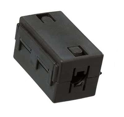
Snap on ferrite for EMI suppression

(Snap on ferrite for EMI suppression)

What Is Electromagnetic Interference (EMI) And How Does It Affect Us?

Electromagnetic interference, abbreviated EMI, is the interference caused by an electromagnetic disturbance affecting the performance of a device, transmission channel, or system. It is also called radio frequency interference, or RFI, when the interference is in the radio frequency spectrum.

All of us encounter EMI in our everyday life. Common examples are:

• Disturbance in the audio/video signals on radio/TV due an aircraft flying at a low altitude

• Noise on microphones from a cell phone handshaking with communication tower to process a call

• A welding machine or a kitchen mixer/grinder generating undesired noise on the radio

• In flights, particularly while taking off or landing, we are required to switch off cell phones since the EMI from an active cell phone interferes with the navigation signals.

EMI is of two types, conducted – in which there is physical contact between the source and the affected circuits, and radiated – which is caused by induction.

The EMI source experiences rapidly changing electrical currents, and may be natural such as lightning, solar flares, or man-made such as switching off or on of heavy electrical loads like motors, lifts, etc. EMI may interrupt, obstruct, or otherwise cause an appliance to under-perform or even sustain damages.

In radio astronomy parlance, EMI is termed radio-frequency interference (RFI), and is a signal within the observed frequency band emanating from other than celestial sources themselves. In radio astronomy, RFI level being much larger than the intended signal, is a major impediment.

Susceptibility to EMI and Mitigation

Analog amplitude modulation or other older, traditional technologies are incapable of differentiating between desired and undesired signals, and hence are more susceptible to in-band EMI. Recent technologies like Wi-Fi are more robust, using error correcting technologies to minimize the impact of EMI.

All integrated circuits are a potential source of EMI, but assume significance only in conjunction with physically larger components such as printed circuit boards, heat sinks, connecting cables, etc. Mitigation techniques include the use of surge arresters or transzorbs (transient absorbers), decoupling capacitors, etc.

Spread-spectrum and frequency-hopping techniques help both analog and digital communication systems to combat EMI. Other solutions like diversity, directional antennae, etc., enable selective reception of the desired signal. Shielding with RF gaskets or conductive copper tapes is often a last option on account of added cost.

RFI detection with software is a modern method to handle in-band RFI. It can detect the interfering signals in time, frequency or time-frequency domains, and ensures that these signals are eliminated from further analysis of the observed data. This technique is useful for radio astronomy studies, but not so effective for EMI from most man-made sources.

EMI is sometimes put to useful purposes as well, such as for modern warfare, where EMI is deliberately generated to cause jamming of enemy radio networks to disable them for strategic advantages.

Regulations to contain EMI

The International Special Committee on Radio Interference (CISPR) created global standards covering recommended emission and immunity limits. These standards led to other regional and national standards such as European Norms (EN). Despite additional costs incurred in some cases to give electronic systems an agreed level of immunity, conforming to these regulations enhances their perceived quality for most applications in the present day environment.

Can capacitors act as a replacement for batteries?

It is common knowledge that capacitors store electrical energy. One could infer that this energy could be extracted and used in much the same way as a battery. Why can capacitors then not replace batteries?

Conventional capacitors discharge rapidly, whereas batteries discharge slowly as required for most electrical loads. A new type of capacitors with capacitances of the order of 1 Farad or higher, called Supercapacitors:

• Are capable of storing electrical energy, much like batteries
• Can be discharged gradually, similar to batteries
• Recharged rapidly – in seconds rather than hours (batteries need hours to recharge)
• Can be recharged again and again, without degradation (batteries have a limited life and hold increasingly lower charge with age, until they can be recharged no longer)

The Supercapacitor would thus appear to be one up on the batteries in terms of performance and longevity, and some more research could actually lead to a viable alternative to conventional fuel for automobiles. It is this concept that created the hybrid, fuel-efficient cars.

However, let us not jump to conclusions without considering all the aspects. For one, the research required to refine this technology would be both time and cost intensive. The outcome must justify the efforts in terms of both time and cost. The negatives must be carefully weighed against the advantages enumerated above, some of which are:

• Supercapacitors’ energy density (Watt-hours per kg) is much lower compared to batteries, leading to gigantically sized capacitors
• For quick charging, one would need to apply very high voltages and/or currents. As an illustration, charging a 100KWH battery in 10 seconds would need a 500V supply with a current of 72,000 Amps. This would be a challenge for safety, besides needing huge cables with solid insulation, along with a stout structure for support
• The sheer size of the charging infrastructure would call for robotic systems, a cumbersome and expensive set up. The cost and complexity of its operation and maintenance at multiple locations could defeat its purpose
• Primary power to enable the stations to function may not be available at remote locations.
Many prefer to opt for the traditional “battery bank” instead. The major problem of lead acid battery banks is the phenomenal hike in the cost of lead and the use of corrosive acid. Warm climates accelerate the chemical degradation leading to a shorter battery life.

A better solution, as often advocated, is to use a century-old technology in which nickel-iron (NiFe) batteries were used. These batteries need minimal maintenance, where the electrolyte, a non-corrosive and safe lithium compound, has to be changed once every 12-15 years. To charge fully, it is preferable to charge NiFe batteries using a capacitor bank in parallel with the bank rather than charging with a lead-acid-battery charger.

Though NiFe batteries are typically up to one and a half times more expensive, lower maintenance cost more than offsets the same over its lifetime.

To summarize, the Supercapacitor technology would still have to evolve in a big way before actually replacing batteries although the former offers a promising alternative to batteries.

image courtesy of eet.com

The Future of Cloud Computing

What is Cloud Computing?

Cloud Computing, an efficient method to balance between dealing with voluminous data and keeping costs competitive, is designed to deliver IT services consumable on demand, is scalable as per user need and uses a pay-per-use model. Business houses are progressively veering towards retaining core competencies, and shedding the non-core competencies for on-demand technology, business innovation and savings.

Delivery Options
• Infrastructure-as-a-Service (IaaS): Delivers computing hardware like Servers, Network, Storage, etc. Typical features are:
a) Users use resources but have no control of underlying cloud infrastructure
b) Users pay for what they use
c) Flexible scalable infrastructure without extensive pre-planning
• Storage-as-a-Service (SaaS): Provides storage resources as a pay-per-use utility to end users. This can be considered as a type of IaaS and has similar features.
• Platform-as-a-Service (PaaS): Provides a comprehensive stack for developers to create Cloud-ready business applications. Its features are:
a) Supports web-service standards
b) Dynamically scalable as per demand
c) Supports multi-tenant environment
• Software-as-a-Service (SaaS): Supports business applications of host and delivery type as a service. Common features include:
a) User applications run on cloud infrastructure
b) Accessible by users through web browser
c) Suitable for CRM (Customer Resource Management) applications
d) Supports multi-tenant environment

There are broadly three categories of cloud, namely Private, Hybrid and Public.

Private Cloud
• All components resident within user organization firewalls
• Automated, virtualized infrastructure (servers, network and storage) and delivers services.
• Use of existing infrastructure possible
• Option for management by user or vendor
• Works within the firewalls of the user organization
• Controlled network bandwidth
• User defines and controls data access and security to meet the agreed SLA (Service Level Agreement).

Advantages:
a) Direct, easy and fast end-user access of data
b) Chargeback to concerned user groups while maintaining control over data access and security

Public Cloud
• Easy, quick, affordable data sharing
• Most components reside outside the firewalls of user organization in a multi-tenant infrastructure
• Access of applications and storage by user, either at no cost or on a pay-per-use basis.
• Enables small and medium users who may not find it viable or useful to own Private clouds
• Low SLA
• Doesn’t offer a high level of data security or protection against corruption

Hybrid Cloud
• Leverages advantages of both Private and Public Clouds
• Users benefit from standardized or proprietary technologies and lower costs
• User definable range of services and data to be kept outside his own firewalls
• Smaller user outlay, pay-per-usage model
• Assured returns for cloud provider from a multi-tenant environment, bringing economies of scale
• Better security from high quality SLA’s and a stringent security policy

Future Projections and Driving User Segments

1. Media & entertainment – Enabling direct access to streaming music, video, interactive games, etc., on their devices without building huge infrastructure.
2. Social/collaboration – cloud computing enables more and more utilities on Face book, Linked-In, etc. With user base of nearly one-fifth of the world’s population, this is a major driving application
3. Mobile/location – clouds offering location and mobility through smart phones enable everything from email to business deals and more.
4. Payments – Payments cloud, a rather complex environment involving sellers, buyers, regulatory authorities, etc. is a relatively slow growth area

Overall, Cloud Computing is a potent tool to fulfill business ambitions of users, and with little competition on date, is poised for a bright future.