Author Archives: Andi

Some Frequently Asked Questions about Raspberry Pi

Q. What is a Raspberry Pi?

A. The Raspberry Pi is a low cost, tiny computer, about the size of a credit card. You can plug your keyboard, mouse and your TV into it, and use it just as you would use a PC. It is capable of playing games, word-processing and working with spreadsheets. You can even watch high-definition video. The composite and HDMI out allows you to connect to any old analog TV, a digital TV or to a DVI Monitor. It is a wonderful device for kids to learn programming.

Q. What are the different models of Raspberry Pi available?

A. As of today (August, 2013) there are two: Model A and model B. Model A has 256MB RAM and one USB port. Model B has 512MB RAM, 2 USB ports and one Ethernet port. When you buy the Raspberry Pi, you get only the board. No SD card or power supply is included, but you can buy them separately. Pre-loaded SD cards are also available.

Q. What are the physical dimensions of the Raspberry Pi?

A. The Raspberry Pi dimensions are 85.6x56x21 (mm) or 3.37×2.21×0.827 (in.), with a small overlap as the connectors and the SD Card project over the edges. The Raspberry Pi weighs about 45 gm.

Q. What is the SoC used for the Raspberry Pi?

A. The SoC or System on Chip is a Broadcom BCM2835. This contains an ARM1176JZFS processor running at 700 MHz, with floating point and a Videocore 4 GPU. The GPU is capable of Blu-ray quality playback and uses H.264 at 40MBits/s. The fast 3D core is accessed using the supplied OpenVG and OpenGL ES2.0 libraries.

Q. How powerful is the Raspberry Pi?

A. The GPU or the Graphical Processing Unit operates with OpenGL ES2.0 and the hardware-accelerated OpenVG libraries, providing 1080p30 H.264 high-profile decode.
The GPU can provide 1Gpixel/s, 1.5Gtexel/s or 24GFLOPS of general-purpose compute along with several texture filtering and DMA infrastructure.
In real world terms, the performance is similar to a 300MHz Pentium 2; however, Raspberry Pi provides much swankier graphics. Overall, the graphical capabilities can be equated to an Xbox 1 level of performance.

Q. Will the Raspberry Pi blend?

A. Yes, extensive virtual simulations have been carried out, there were no failures.

Q. Is it possible to overclock the Raspberry Pi?

A. Most of the devices run comfortably at 800MHz. The latest operating system has options of changing the options for overclocking on the first boot. If you run “raspi-config” you can change the options again at any time, and your warranty stays intact. However, these settings are experimental and not every board can be expected to run stably at the highest setting. To restore stability, try reducing the settings for overclocking.

Q. How do you boot the Raspberry Pi?

A. You need a pre-loaded SD card to boot. After the initial boot, a USB HD can “take over”. The root partition on the SD card must contain the operating system. Currently Debian Linux is the default distribution, but you can use any other ARM Linux distro available on the downloads pages.

Q. What are the power requirements of the Raspberry Pi?

A. The device is powered by 5V from the micro USB. To switch on, simply plug in the USB, to switch off, remove the power.

Let Raspberry Pi Make It to the Movies through XBMC

The Raspberry Pi is capable of HD video. Won’t it be great if you could playback your Blu-ray movie collection through Raspberry Pi on to your HD TV or monitor? That would be possible if you knew how to let Raspberry Pi run XBMC.

What is XBMC?

XBMC is a software media player and entertainment hub, and the best part is you do not need to pay anything to get it, as XBMC is free and open source (GPL). As a media player, XBMC has almost everything you will need, right from TV and remote controls, to support for digital media files from local and network storage media including the internet. You can play and view most digital media files such as podcasts, music and videos.

There is not much that XBMC misses. You get to play all your music files in mp3, flac, wav and wma formats. You can watch movies in all the main video formats including streamable online media. You can keep track of your progress of season views and episodes of TV shows. You can import pictures into a library for browsing as in a slideshow, and you can record live TV all from the nice GUI interface that XBMC has.

Step 1: Download XBMC

You will need to download an image of XBMC, which is available as “debian-xbmc-24-04-2012.zip” and you can get it here. Unzip the file to get to the image.

Step 2: Write the Image on to an SD Card

If you are on Linux or OSX, open up a terminal and navigate to the folder containing the downloaded image. To write to an SD card, you have to enter the following command –

dd bs=1m if=debian-xbmc-24-04-2012.img of=/dev/rdisk1

Note that ‘/dev/rdisk1’ depends on the type of PC you are using.

If you are still on Windows, you need the Win32DiskImager utility program to write the image to the SD card in the device box.

Step 3: Make Space on the SD Card

The image written to the SD Card will be about 2GB, leaving about 60MB free space. This is not enough for XBMC to operate properly. Use Gparted, which is the Debian partition editor to expand the free space. Assuming you have a 16GB card on which you installed the OS and XBMC, there is still 13GB space left over. Go into Gparted, and expand the Linux swap partition to cover the 13GB. That will allow XBMC to use the free space.

Step 4: Start Action

Plug in the SD card into your Raspberry Pi, and boot it up. At the command prompt, type –

XBMC

and you should be able to see the following –

Note that XBMC is still an alpha release, and is somewhat fragile. It might lock up or not start at all. This is expected and you may need to restart Raspberry Pi over again to get XBMC play properly.

Try out all your music, video and other programs including your favorite TV shows, and you will be surprised at the quality of the output from the combination of XBMC and Raspberry Pi.

How RTPs Help To Save Expensive PCBs from Thermal Runaway PowerFETs

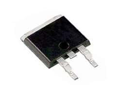
powerfetAlthough powerFETs or power Field Effect Transistors are very robust devices used in the automotive industry – they have their limitations. In the automotive environment, powerFETs go through the tortures of extreme temperature variations together with severe thermo-mechanical stresses. They face noisy short circuits, high arcing, intermittent shorts as well as inductive loads. These shocks can fatigue the device over time, and it can fail in a short, an open or resistive mode.

For example, if the maximum operating voltage of a powerFET is exceeded, failure happens very quickly. The powerFET goes into an avalanche breakdown once the voltage rating goes beyond the maximum allowed. If the energy within the transient overvoltage is more than the rated avalanche energy level, the device will start to fail resulting in generation of smoke, flame or it may even be de-soldered.

In some cases, the powerFET while failing may generate precarious temperatures through I2R heating. This may cause a thermal runaway for the device, but the resulting current may not be large enough to cause failure of a standard fuse protecting the powerFET. This mode of failure is of particular concern, for not only the powerFET, but also for the PCB or the Printed Circuit Board. A power of as little as 10 Watts may generate localized hot spots of above 180°C, which can damage the glass PCB’s epoxy structure leading to a thermal event.

Tyco Electronics has developed a Reflowable Thermal Protection or RTP, which is a reliable and robust surface mount thermal protector to prevent thermal damage on PCBs caused by failing power electronics. This is a secondary thermal protection device, which can replace several components such as redundant powerFETs, heavy heat sinks and relays currently used for such protection in the automotive designs.

To work effectively, the RTP device has to be placed in series and on the power line, very close to the FET. This allows the device to track the temperature of the FET and disrupt the current by opening the circuit before the thermal runaway condition generates a thermally destructive condition on the PCB. Under normal conditions, the RTP device has a low resistance, typically about 0.6mOhm.

Whenever the RTP device detects the generation of unsafe temperatures because of the failure of a power component or any other board defect, it interrupts the current and prevents a thermal runaway condition that could lead to critical damage. An RTP200 device typically opens (high resistance condition) at 200°C, which is a temperature above the normal operating temperature, but below the Lead-free solder reflow temperature.

It may seem like a paradox that the RTP device operates at 200°C but can withstand Lead-free soldering temperatures of 220°C. This is because the RTP is not in an active state unless it has been armed by passing a specific current through it for a specified amount of time. Before it is armed, the RTP can withstand three Lead-free solder reflow steps before it operates. The electronic arming procedure is one-time only and can be implemented to occur automatically or during system testing.

The Emergence of BBB: the BeagleBone Black

Many a time we have wished our bulky PCs that occupy so much of the desktop space could somehow be magically squeezed into a portable unit. Although such systems are there including the new smartphones and tablets, their sky-high prices are very discouraging for most of us.

Despair not, for such a package has arrived and is well within the reach of an average person’s pocket. Moreover, if you are technically oriented, you could build one yourself. Texas Instruments has provided the core processor and BeagleBoard has provided the packaging. The result is the low-cost, low power, fan-less, single-board computer called the BeagleBone, a latest addition to the BeagleBoard family.

The low-cost, fan-less, low power, single-board computers from BeagleBoard utilize the Texas Instruments’ OMAP3530 application processor. This offers laptop like performance and facility for expansion, without the bulk, the noise and the expense that are typical of desktop machines. Within the OMAP3530, there is a 600MHz ARM Cortex-A8 Micro Controller Unit (MCU), which predicts branches with high accuracy and a 256KB L2 cache memory.

The on-board USB 2.0 OTG port serves a dual purpose; you can transfer data out from the board or allow the board to read data in from an external source. Although the board has a separate 5V DC power socket, power to the board can be supplied through the USB port as well. The board also has a mini-A connector, to which you can connect standard PC peripherals using a standard-A to mini-A cable adapter. A DVI-D connector allows a HDMI display to be connected using a HDMI to DVI-D adapter. The third connector is the MMC/SD/SDIO card connector. To give you the best graphics experience, the BeageBoard has a state of the art POWERVR graphics hardware, which will render 10 million polygons each second.

For people who were not satisfied with the power of the BeagleBoard single-board computer, BeagleBoard has added the BeagleBone Black or BBB. This is the newest addition to the BeagleBoard family, and continues the saga of the low-cost, low power, single-board computers. To provide the additional features, an advanced MCU, the Texas Instruments’ Sitara AM3359 has been used. This is an ARM Cortex-A8 32-bit RISC processor, featuring a speed of 1GHz, and gives BBB the power along with a 512-MB DDR3L 400MHz SDRAM and 2GB 8-bit eMMC on-board flash memory. This frees up the micro SD card slot for further expansions.

The 92-pin headers are Cape compatible, meaning the existing family of cape plug-in boards can be used as well. The on-board HDMI allows direct connection to monitors and TVs. External electronics circuitry can be controlled by the UART0 serial port. For connecting to the Internet, a 10/100 RJ45 Ethernet connector has been provided.

You will need the latest Angstrom distribution eMMC flasher to load the latest Linux distribution. This is a 4GB image, that has to be uncompressed using unxz and written to a micro SD card. Connect an HDMI monitor, and after plugging in the micro SD card in the slot of the BBB, you can power on your single-board Linux computer. Take care to hold the boot button on while powering, and watch the LEDs on the BBB flash and then stay on.

Raspberry Pi projects to inspire you!

In How Many Ways Can You Use Your Raspberry Pi?

Many of you who already have the tiny Linux PC – the RaspBerry Pi – affectionately also known as RBPi, are already using it in your own way to write and test code and to build controllers. The Raspberry Pi is a stripped-down Linux computer, running an ARM-Based CPU, with a graphics processor and many pins and ports, which you can use. We present here many extraordinary ways that owners have Raspberry Pi developed new projects.

Well, taken straight out of its packing, you can plug your TV into Raspberry Pi, connect a keyboard and try some of casual games, video streaming and word processing. All this must have become pretty mundane for Simon Cox after sometime, since he decided to build a supercomputer out of many Raspberry Pis. The computer engineer from UK’s University of Southampton tied 64 Raspberry Pis together. His 6-year old son built the rack for the supercomputer with his LEGO set!

Have you ever thought of mixing music, vegetables, wordplay and Raspberry Pi? Not likely, but Scott Garner has. On his BeetBox, you can play drumbeats on real beets when you touch them. He has used capacitive touch sensors for communicating between the beets and his Raspberry Pi. His only complaint is that the beets dry off and have to be replaced.

If Raspberry Pi is a Linux computer, surely it can be used as a palmtop. A similar thought must have prompted Nathan Morgan to build his Pi-to-Go Palmtop. Sporting a 640×480 display, a touchpad, support for HDMI, Bluetooth, Wi-Fi and a 64-GB solid state drive, it is a perfectly portable Raspberry Pi. However, some of you may not find it to be the thinnest or the lightest, but it is enough as a proof of concept to its maker.

Beer and Raspberry Pi may not be an obvious match, but that did not deter a company Robofun Create in making a QWERTY keyboard from 44 beer cans from a Prague-based brewery. If you are over 21, you are allowed in the bar and you can tap the tops of the beer cans to let Raspberry Pi produce the corresponding alphabets on a plasma screen overhead. Of course, the alphabets are also marked on the tops of the beer cans.

Movies such as “The Life of Pi” can also be inspiring. FishPi is planning to set Raspberry Pi adrift in a boat that will be crossing the mighty Atlantic. Raspberry Pi will not be floating idly, but has to control the boat’s navigational system. In short, Raspberry Pi will be the captain, navigator and sailor for the 20-inch long boat. Additionally, it has to collect scientific measurements for which it will be powered by a 130-watt solar panel. We wish Raspberry Pi all success on its solo sailing trip.

Like most people who buy nice things on impulse, such as an Raspberry Pi, are stuck for want of a suitable project. Jeroen Domburg had the same problem, until he came up with the Teeny Tiny Arcade. His is probably the smallest gaming cabinet built in an arcade style. Jeroen cut the plastic with laser to make his cabinet and it has a 2.4-inch TFT Display.

Let Your Raspberry Pi Take Pictures of the Earth

How About Letting Your Raspberry Pi Take Pictures of the Earth?

Many many years ago, before cameras came to be associated with lenses, people captured images on film using a pinhole on the camera. This technique is still in use today. It’s called heliography and it requires long to very long exposure times – sometimes as much as 24 hours to six months. The results are rather stunning, as you can see.

Unless you have photography as a hobby, you may not be able to spare much time and may not have equipment suitable for heliography. However, taking pictures of the earth is quite an exciting project, and since you have Raspberry Pi, why not let the tiny Linux computer do it?

That is exactly what Dave Akeman planned to do. He created the Raspberry Eye-in-the-Sky project that sent Raspberry Pi and a bunch of components out into the atmosphere where the weather balloons go and burst themselves. The payload consisted of a Raspberry Pi, a camera and a tracker, powered by a few AA batteries. The pictures, taken while the camera was in the sky, are spectacular and amazingly crisp.

Dave changed the regulator on the Raspberry Pi and modified it so the computer could work on 3V instead of 5V, to allow the batteries to last longer. He embedded the entire electronics in a foam replica of the Raspberry Pi logo, with the camera peeping out from the bottom. The foam was for softening the landing of the package when it hit the ground after the balloon burst. Dave also put in a parachute so the package would come down smoothly.

Dave had to take permission from the CAA for the Hydrogen balloon that would carry his Raspberry Pi camera payload into the atmosphere. He used the latest Pi camera software and changed the code to make it take three types of images each at about one minute interval. One small image is taken for the first radio channel, one medium image for the second radio channel and one hi-resolution image is stored on the SD Card onboard. Additionally, Dave configured the camera to work in matrix-metering mode instead of spot metering, as this gave better resolution images.

The balloon and its camera payload went up one sunny morning, near Tetbury, UK. People from France, Holland and Northern Ireland monitored the Raspberry Eye-in-the-Sky broadcast. The image quality throughout the 3-hour flight time was excellent. The flight path, with the wind guiding it, had quite a few changes of direction and some loops. The package went up to about 24.5 miles in height finally landed near the city of Swindon about 22 miles away from Tetbury.

As the launch was delayed by more than 2 hours, the Raspberry Pi package missed the original predicted landing spot, since the wind pattern had changed in the meantime. In addition, a resident of Swindon found the package as it landed near him, and took it home. He then called up Dave after finding his telephone number on the package. That solved the initial mystery as to how the Raspberry Pi package travelled to another location after it had landed.

How to measure temperature with a Raspberry Pi

Looking for another project to make with a Raspberry Pi? You can use your Raspberry Pi to measure temperature. Not only at a single point, but also at maximum of 20 points simultaneously. Of course, you will need 20 individual sensors for doing that. Raspberry Pi will poll all the 20 sensors one after the other, and read the temperature from each of the sensors.

If you are wondering how complicated it would be to wire up 20 sensors to the Raspberry Pi, you can relax, since you need only three wires in all. One of the wires will carry power to the sensors, one wire will be the ground or return path and the third wire is a unique 1-wire interface to control the sensor and to read the temperature measured by it.

This wonder sensor is a High-Precision 1-Wire Digital Thermometer, DS18S20, with a measurement range of -55°C to +125°C (-67°F to +257°F), a thermometer resolution of 9-bits and an accuracy of ±0.5°C from -10°C to +85°C. Maxim Integrated makes this thermometer and the smallest size is a little larger than a matchstick head (TO-92).

Not only can this tiny fellow read the temperature, it stores them in its non-volatile memory and can present them either as °C or as °F. You can set temperature limits in its memory and DS18S20 will tell you when the temperature it is monitoring goes beyond the programmed limits. You can use this thermometer with the Raspberry Pi to control thermostats, industrial systems, consumer products or any thermally sensitive system.

At this point, you may be wondering if there is only one single wire for all the 20 sensors, how is the Raspberry Pi able to differentiate the twenty temperature readings. Maxim has programmed each of the sensors with a unique serial number, and when Raspberry Pi wants to read the temperature from a specific sensor, it simply asks for it by the serial number of that sensor. Only the sensor whose serial number the Raspberry Pi queries, sends the temperature data, all the others remain silent.

The Raspbian Linux distribution that you are using in your Raspberry PI already has all necessary kernel modules installed for accessing the 1-wire bus. The programming details are rather simple and you can refer to them here.

What else can you do with a DS18S20 and Raspberry Pi? You may be measuring temperature at a remote place, or there is no space for the extra power supply to the DS18S20. So, instead of supplying power separately, you could make DS18S20 “steal” power from the 1-Wire bus. For this, you must connect the VDD pin of the DS18S20 to ground. According to the datasheet, do not use the parasitic mode for measurements above 100°C, as the DS18S20 will not be able to sustain communications.

If you have programmed temperature limits for some of the DS18S20s, they will raise a flag if the temperature they are sensing goes beyond the set points. By polling for the flags, Raspberry Pi can know, which sensor is sensing temperatures beyond its set point.

How Does A Real Time Spectrum Analyzer Work?

We use an oscilloscope to view variations of input voltage with time. We use a spectrum analyzer to view variations of input voltage with frequency. Measurements in the frequency domain are possible with traditional architectures such as the super heterodyne, swept-tuned spectrum analyzer. Earlier such instruments were made purely with analog components. Modern instruments have evolved with digital elements such as Analog to Digital Converters (ADCs), Digital Signal Processors (DSPs) and microprocessors.

However, the basic principle of working remains the same, and for observing controlled, static signals, it is the best suited. The signal analyzer makes amplitude vs. frequency measurements. The signal of interest is down-converted and swept through the passband of a Resolution Bandwidth Filter (RBW). The signal then passes through a detector that calculates the amplitude of each frequency point in the selected span.

Although this method provides a high dynamic range of measurements, it can only calculate the amplitude data for one frequency point at a time. This assumes that while the analyzer is making one sweep, there is no significant change to the signal being measured. Therefore, the measurements are suitable for relatively stable input signals that remain unchanging. If there were fast changes in the signal, statistically there would be a probability that some signals were missed.

This spectrum analyzer architecture therefore, does not provide a reliable way to discover transient signals, which leads to a prolonged time and effort for troubleshooting modern RF signals; this lead to the development of the Real Time Spectrum Analyzer.

To analyze signals in real-time, therefore, the analysis must be carried out fast enough so that all signal components in the frequency band of interest are accurately processed. For this, two things are necessary. First, the sampling of the input signal must be fast enough and satisfy the Nyquist criteria, which implies the sampling frequency must be more than two times the bandwidth of interest.

Second, all computations must be performed fast enough and continuously so that the output of the analysis always matches and keeps track of the changes in the input signal.

The architecture of the Real-Time Spectrum Analyzer or RSA is so designed that it can overcome the measurement limitations of the simple Spectrum Analyzer (SA). The RSA addresses the challenges that transients and dynamic RF signals pose to signal processing by the SA. The RSA does this by real-time digital signal processing before the storing the results in memory.

This way, the user is able to see and capture transient events invisible to other types of instruments, and he can trigger on such events allowing them to be selectively captured in the memory. The data in the memory can then be separately analyzed extensively in many other domains with the help of batch processing. The real-time DSP engine is also helpful in signal conditioning and calibration of many types of analysis.

Modern RSA architecture uses a combination of both analog and digital signal processing for converting RF signals into measurements that are calibrated and time-correlated. Input RF signals are converted into analog IF signals that are filtered by a bandpass filter before they are digitized.

Carbon Nanotubes Can Reduce the Price of Fuel Cells

Like all other batteries, fuel cells too use chemicals to create electricity. However, in contrast to ordinary batteries, the advantage of fuel cells is their very high energy density. The energy they produce is high compared to their weight when compared with other batteries.

The energy density of the fuel cells comes at a high price. The platinum catalysts in the fuel cells are very expensive. Now, scientists at the Stanford University have developed a technique to replace the platinum with carbon nanotubes, which makes for an attractive and low-cost solution.

At Stanford, scientists have used multi-walled carbon nanotubes, which are riddled with impurities and defects on the outside. Such nanotubes may be used to replace the expensive platinum catalysts presently used in metal-air batteries and fuel cells.

Since platinum is very expensive, it is impractical for commercialization on a large scale. Scientists have been researching to find a cheaper alternative for the past several decades. The price of Platinum is anywhere from $800 to $2,200 an ounce. So far, the most promising low-cost alternative has been the carbon-nanotubes.

A carbon nanotube is a rolled-up sheet of pure carbon. This is called grapheme, and only one atom thick. An impression of the thinness can be gaged by the fact that a human hair is more than 10,000 times thicker than a carbon nanotube. Apart from being inexpensive to produce, carbon nanotubes of graphene are excellent conductors of electricity.

For replacing the Platinum catalysts, the Stanford scientists used multi-walled carbon-nanotubes. These had two or more concentric tubes nesting together. The catalytic activity of the nanotubes was enhanced with a shredded outer wall, with the inner walls intact. Moreover, this did not reduce their ability to conduct electricity.

Although typical carbon-nanotubes do not have many defects, to promote the formation of catalytic sites, defects had to be deliberately introduced in the outer walls of the carbon-nanotubes. The net effect of the introduction of the defects was they rendered the nanotubes as very active for catalytic reactions.

If the carbon-nanotubes are thinner than human hair, how did the scientists cause defects in the outer wall, leaving the inner walls intact? They treated the multi-walled nanotubes in a chemical solution. With this treatment, the outer nanotube unzipped partially and formed nano-sized graphene pieces. The inner nanotubes remained mostly intact, and the graphene pieces clung to these inner tubes.

Scientists then added a few impurities such as nitrogen and iron to the outer wall to make it very active for catalytic reactions. The nanotube maintained its integrity because of the inner walls, and the inner walls provided the necessary path for electrons to move. The overall effect was a very active outside wall along with excellent electrical conductivity. This advantage would not have been possible with just a single wall carbon-nanotube, as the damage to the wall would have impaired its electrical property as well.

Metal-air batteries and fuel cells require Platinum catalysts to speed up chemical reactions for converting oxygen and hydrogen to water. The catalytic activity of the partially unzipped, multi-walled nanotubes was very close to Platinum. Scientists are planning to produce fuel cells with very high energy density that can last for a long time.

What Is Ultrasonic Ranging?

Ultrasonic technology has some unique advantages over other types. With ultrasonic methods, you can solve several application problems that become cost prohibitive or simply cannot be solved by other methods. Some of these are: long range detection, broad area detection, widest range of targeted materials and non-contact distance measuring.

In simplest terms, ultrasonic ranging is a method of echo-location. Most of us have used echo-location to know the distance to the cliff producing the echo, the distance of the thundercloud or the depth of a deep well. The principle is simple, note the time taken for the sound to travel and multiply it with the speed of sound. For example, you may hear the sound of thunder 3 seconds after you see the flash. The source of the sound is then 3 times 330 or 990 meters away, as sound travels roughly at 330 meters every second in air. Thunder is visible almost instantaneously, as light travels nearly 1,000,000 times faster than sound does.

The only difference in ultrasonic ranging is the use of sound frequencies that are beyond the range of normal human hearing. Young humans can hear sounds with frequencies ranging from 20 Hz to 20 KHz, with the upper limit dropping off to 15 KHz or even to 10 KHz with advancing age. Frequencies of 30 KHz to 40 KHz are common in ultrasonic ranging.

In ultrasonic ranging, a burst of high-frequency sound is generated, and a timer is started simultaneously. The timer stops as soon as the echo arrives. The burst of sound leaves the transmitter, hits the target object and returns to the receiver. Therefore, it took only half of the total time elapsed for the sound to reach the target object. This half-time multiplied by the speed of sound in the medium gives the distance of the target object from the source of the sound.

Although the sensors for producing the ultrasonic sound and for receiving it may take many complicated shapes depending on the actual application, for general purpose ultrasonic ranging, the sensor module looks like:

The associated electronics on board the sensor module consists of a microprocessor programmed to generate a burst of sound on trigger. The microprocessor also measures the time taken to receive the echo (time of flight) and thereby calculates the distance.

Ultrasonic ranging is mostly used in two ways for locating objects – proximity detection and precise range measurement. In proximity detection, any object passing within the preset range will be detected and the module will generate an output signal. The detection will be independent of object size, material or degree of reflectivity.

Ultrasonic ranging is also used for precise measurements of an object moving to and from the sensor. As explained earlier, the time of flight is measured for calculating the distance between the sensor and the object. By repeatedly sending sonic bursts and measuring the echo received, the distance of change is continuously calculated and displayed.

Depending on the frequency of sound generated by the ultrasonic transducer, the sensing range can vary from a few centimeters to about 10 meters.